EasyManuals Logo

Stober SC6 Series User Manual

Stober SC6 Series
219 pages
To Next Page IconTo Next Page
To Previous Page IconTo Previous Page
Page #103 background imageLoading...
Page #103 background image
STOBER 9 | Connection
05/2019 | ID 442790.01
103
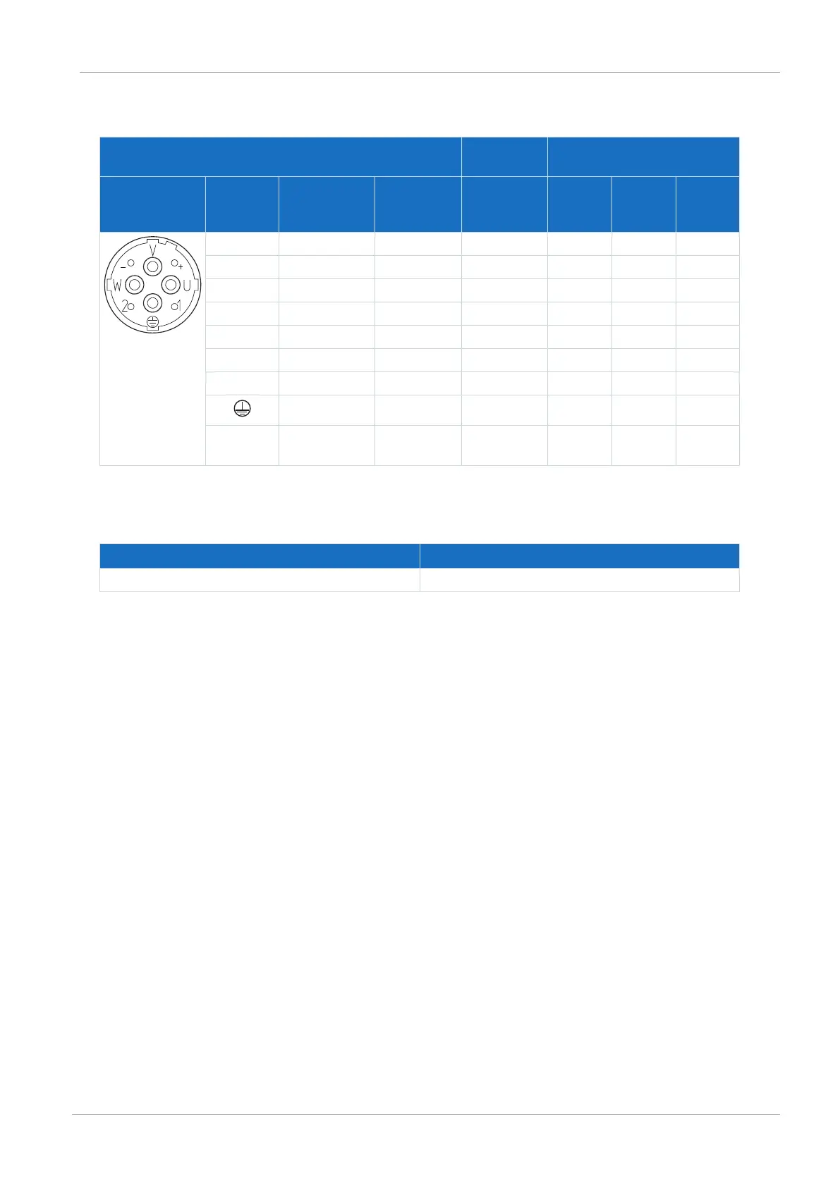
Power cables – con.40 plug connectors
Motor
(1)
Cable
(2)
Drive controller
(3) – (5)
Motor
connection
diagram
Pin Designation Int. motor
Core color
Core No./
Core color
Pin
X20
Pin
X300
Pin
X2
U 1U1 BK 1 1 — —
V 1V1 BU 2 2 — —
W 1W1 RD 3 3 — —
+ 1BD1 RD 5 — 5 —
− 1BD2 BK 6 — 6 —
1 1TP1
a)
BK 7 — — 7
2 1TP2
a)
WH 8 — — 8
PE GNYE GNYE 4 — —
Housing Shield — — Shield
contact
— —
Tab. 110: con.40 power cable pin assignment
a) PTC
Length x [mm] Diameter y [mm]
99 46
Tab. 111: con.40 connector dimensions

Table of Contents

Other manuals for Stober SC6 Series

Questions and Answers:

Question and Answer IconNeed help?

Do you have a question about the Stober SC6 Series and is the answer not in the manual?

Stober SC6 Series Specifications

General IconGeneral
BrandStober
ModelSC6 Series
CategoryController
LanguageEnglish

Related product manuals