9 | Connection STOBER
106
05/2019 | ID 442790.01
Encoder cables – con.17 plug connector
The power supply is buffered for EnDat 2.2 digital "EBI 1135" and "EBI 135" inductive encoders with a multi-turn function.
In this case, pin 2 and pin 3 of the motor are assigned to the U
2BAT
buffer battery. Note that the encoder cable must not be
connected to the encoder interface of the drive controller, but rather to the AES battery module for these encoders.
Motor
(1)
Cable
(2)
Drive controller
(3)
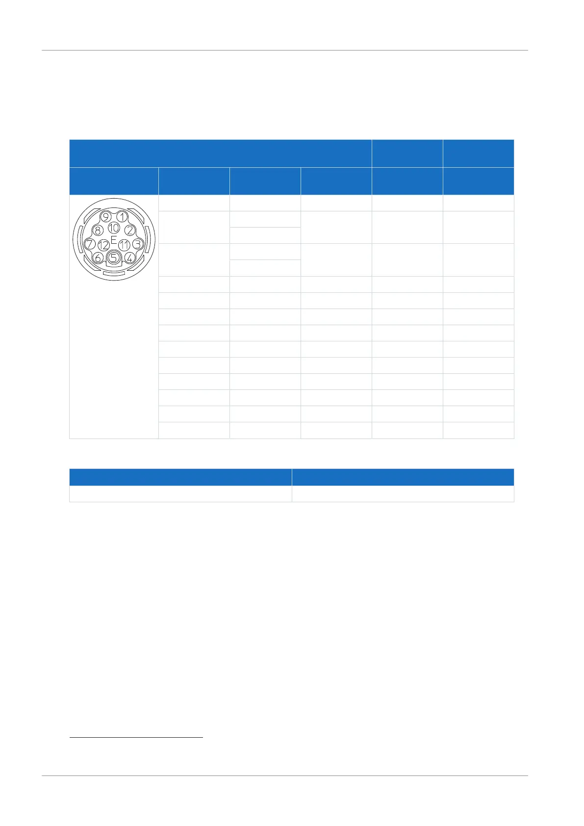
Connection diagram Pin Designation Core color Core color Pin
X4
1 Clock+ VT YE 8
2 Sense U
2
BU PK 12
U
2BAT+
15
3 — WH GY 3
U
2BAT-
16
4 — — — —
5 Data− PK BN 13
6 Data+ GY WH 5
7 — — — —
8 Clock− YE GN 15
9 — — — —
10 GND WHGN BU 2
11 — — — —
12 U
2
BNGN RD 4
Housing Shield — — —
Tab. 114: con.17 encoder cable pin assignment, EnDat 2.1/2.2 digital
Length x [mm] Diameter y [mm]
56 22
Tab. 115: con.17 connector dimensions
15
Only relevant for EBI encoders
16
Only relevant for EBI encoders

 Loading...


