Stonex R25/R25LR Total Station - User Manual 72
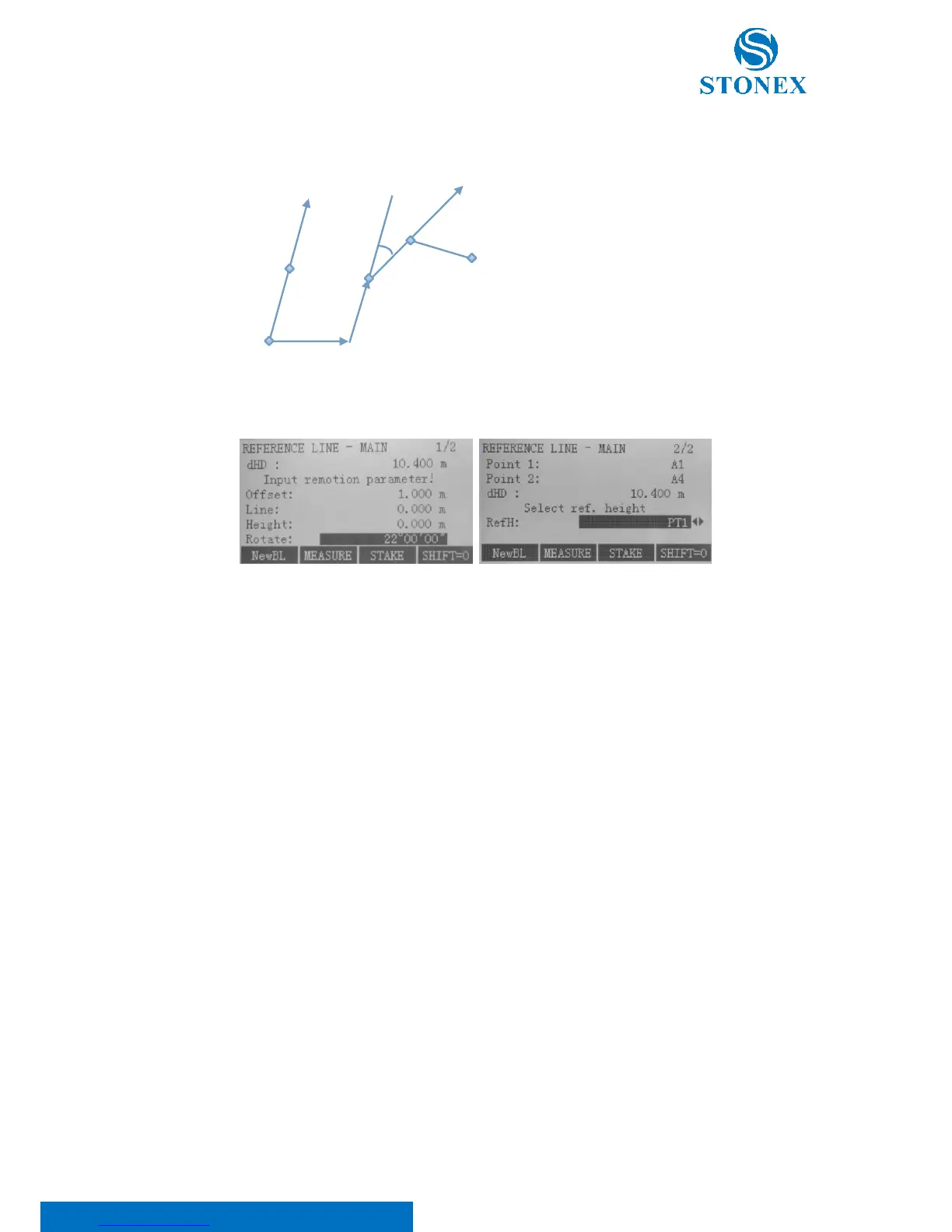
After defined, the baseline can be offset longitudinally, in parallel and perpendicularly or rotated. This new line is
called the reference line: all measured data refers to the reference line.
Input remotion parameter in both the pages, scrolling through the {PAGE} key.
Here:
dHD: Represents the horizontal distance between the two points, used to define the baseline;
Offset: Parallel offset of the reference line to the right, referred to the base line (BP1-BP2);
Line: Longitudinal offset of the reference point of the reference line in the direction of base point BP2;
Height: Height offset. The reference line is higher than the selected reference height;
Rotate: clockwise rotation of the reference line around the reference point;
RefH: Select reference height; use ◄/► keys to choose between:
• PT1: Height differences are computed relative to the height of the 1st base point;
• PT2: Height differences are computed relative to the height of the 2nd base point;
• Interpolation: Height differences are computed along the reference line;
• NoH: Height differences are not computed and shown.
Then, decide to measure or stake out. Press F2[MEASURE] key to activate Line & Offset measuring or press F3[STAKE]
key to start the application to stake out. Use F1[NewBL] to change the base line.