Duplex Operation
The RJ45 ports will auto-sense for Full or Half duplex operation; the fiber ports are configured
for full duplex operation. On managed switches the duplex setting is software configurable.
NOTE: Fiber devices with half duplex settings will communicate with the switch in most situations.
Network Device Check
The industrial Ethernet switches and media converters support 10/100BaseT or 10/100/100
Base T on the RJ45 (copper) ports and 100BaseFX or gigabit Ethernet on the fiber optic ports
depending on model. Make sure you connect the appropriate devices to each port.
NOTE: The following AutomationDirect PLC Ethernet Modules are not compatible with the Stride Ethernet switches
and Media Converters with fiber optic connections because the modules have a speed of 10BaseF (fiber optic) only:
Ethernet Communications Module, p/n H2-ECOM-F & H4-ECOM-F; Ethernet Base Controller Module, p/n H2-EBC-F &
H4-EBC-F; Ethernet Remote Master Module, p/n H2-ERM-F & H4-ERM-F.
Verifying Connectivity
After all Ethernet and/or fiber connections are made, check the LEDs corresponding to the
ports that each of the devices are connected to. Ensure that for each port that is in use, the LED
is on or blinking. If a port LED is off, go back and check for connectivity problems between
that port and the network device connected to that port. In addition, the color of the LED
should indicate the speed at which your device is connected (see prior section on LEDs).
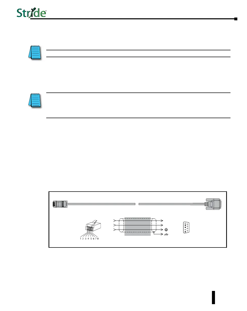
Serial Console Port Wiring
An optional way to configure the managed switch is through the RJ45 console RS232 port.
Wire a serial console cable as shown below to make a connection between a COM port on your
PC (DB9 male) and the RS232 port of the managed switch (RJ45 female).
1-29
Chapter 1 - Hardware
Stride Industrial Ethernet Switches User Manual 2nd Ed. Rev. B
Serial Configuration Cable
Switch RJ-45
Serial Port
PC Serial Port
6
1 = do not use
2 = RXD
3 = TXD
4 = do not use
5 = Signal GND
6 = do not use
7 = do not use
8 = do not use
9 = do not use
5
4
TXD
RXD
GND
2
3
5
1
RXD
TXD
shield
Wiring Diagram
Note: Use the above wiring diagram to make your own cable. We recommend using 22 AWG shielded cable.
1 = do not use
2 = do not use
3 = do not use
4 = Signal GND
5 = RXD
6 = TXD
7 = do not use
8 = do not use
RJ45 8-pin
Phone Plug
(8P8C)
9-pin
D-sub
(female)
1
9
 Loading...