I
CAMSHAFT
MECHANICAL
B:
INSTALLATION
1)
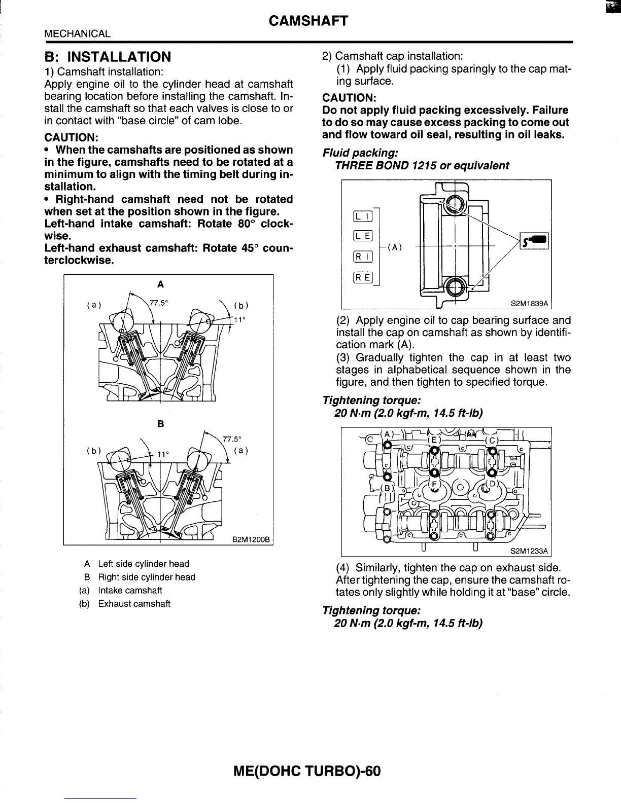
Camshaft installation:
Apply engine oil to the cylinder head at camshaft
bearing location before installing the camshaft. In-
stall the camshaft
so that each valves is close to or
in contact with “base circle” of cam lobe.
CAUTION:
When the camshafts are positioned as shown
in the figure, camshafts need to be rotated at a
minimum to align with the timing belt during in-
stallation.
Right-hand camshaft need not be rotated
when set at the position shown
in
the figure.
Left-hand intake camshaft: Rotate
80”
clock-
wise.
Left-hand exhaust camshaft: Rotate
45”
coun-
terclockwise.
A
h
2)
Camshaft cap installation:
(1)
Apply fluid packing sparingly to the cap mat-
ing surface.
CAUTION:
Do
not apply fluid packing excessively. Failure
to do
so
may cause excess packing to come out
and flow toward oil seal, resulting
in
oil leaks.
Fluid packing:
THREE BOND 1215
or
equivalent
(2)
Apply engine oil to cap bearing surface and
install the cap on camshaft as shown by identifi-
cation mark (A).
(3)
Gradually tighten the cap in at least two
stages in alphabetical sequence shown in the
figure, and then tighten to specified torque.
20 N.m (2.0 kgf-m, 14.5 ft-16)
Tightening torque:
I
U
U
S2M
1233A
A
Left
side
cylinder
head
B
Right
side cylinder
head
(a)
Intake camshaft
(b)
Exhaust
camshaft
(4)
Similarly, tighten the cap on exhaust side.
After tightening the cap, ensure the camshaft ro-
tates only slightly while holding it at “base” circle.
20 Nom (2.0 kgf-m, 14.5 ft-16)
Tightening torque:
ME(D0HC
TURBO)-60