CYLINDER BLOCK
MECHANICAL
Bearing size
(Thickness at cen-
ter)
5.
CONNECTING
ROO
1)
Replace the connecting rod,
if
the large or small
end thrust surface is damaged.
2)
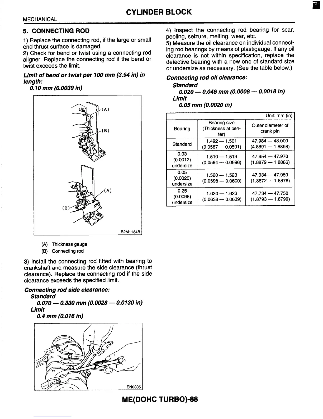
Check for bend or twist using a connecting rod
aligner. Replace the connecting rod
if
the bend or
twist exceeds the limit.
Limit
of
bend or twist per
100
mm (3.94 in) in
length:
0.10
mm (0.0039 in)
Outer diameter
of
crank pin
n
B2M1184B
(A)
Thickness gauge
(B) Connecting rod
3)
Install the connecting rod fitted with bearing to
crankshaft and measure the side clearance (thrust
clearance). Replace the connecting rod
if
the side
clearance exceeds the specified limit.
Connecting rod side clearance:
Standard
Limit
0.070
-
0.330 mm
(0.0028
-
0.0130
in)
0.4 mm
(0.016
in)
4)
Inspect the connecting rod bearing for scar,
peeling, seizure, melting, wear, etc.
5)
Measure the oil clearance on individual connect-
ing rod bearings by means of plastigauge.
If
any oil
clearance
is
not within specification, replace the
defective bearing with a new one of standard size
or undersize as necessary. (See the table below.)
Connecting rod oil clearance:
Standard
Limit
0.020
-
0.046
mm
(0.0008
-
0.0018
in)
0.05
mm
(0.0020
in)
I
Unit: mm (in)
I
I
Bearing
I
Standard
(0.001 2)
(0.0020)
undersize
undersize
(0.0098)
undersize
1.492
-
1.501 47.984
-
48.000
1.510-1.513 47.954
-
47.970
1.520
-
1.523 47.934
-
47.950
1.620
-
1.623 47.734
-
47.750
ME(
DOH C
TU
R
BO)-88