DIAGNOSTICS FOR ENGINE STARTING FAILURE
ENGINE (DIAGNOSTICS)
io
to
step
3.
_____~
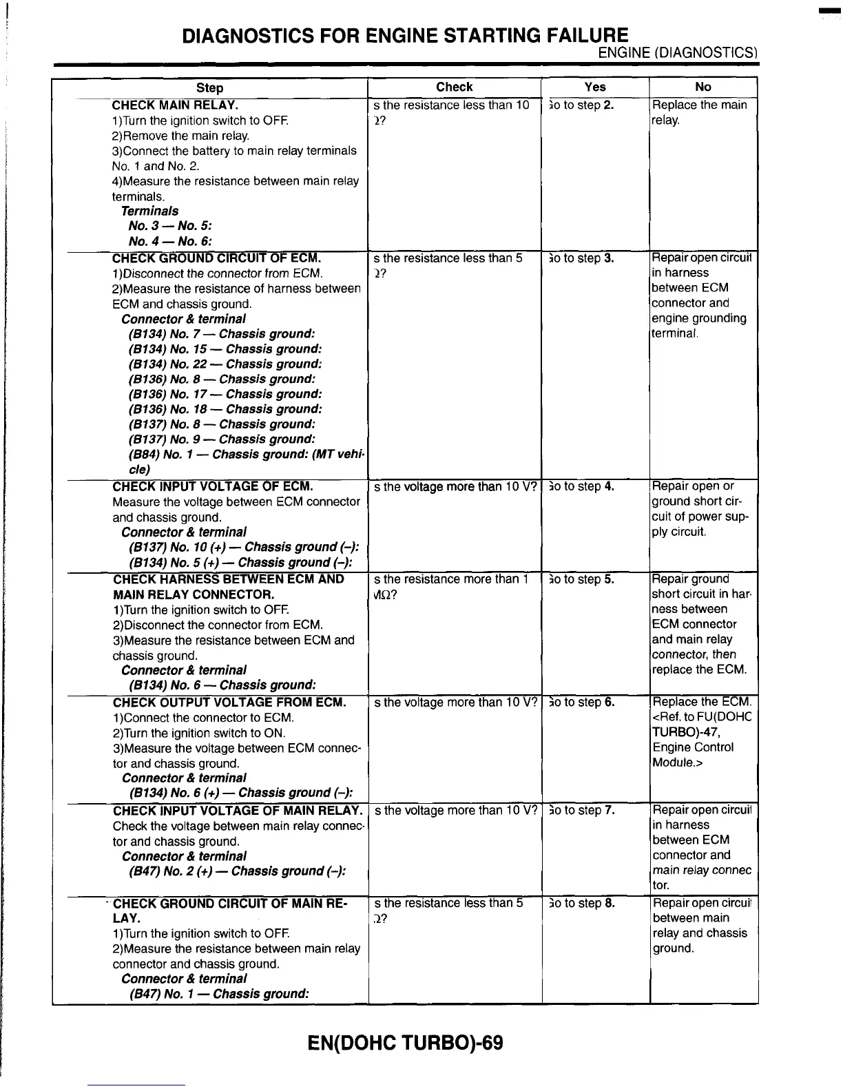
Step
CHECK MAIN RELAY.
1)Turn the ignition switch to
OFF.
2)Remove the main relay.
3)Connect the battery
to main relay terminals
No.
1
and
No.
2.
4)Measure the resistance between main relay
terminals.
Terminals
NO.
3
-
NO.
5:
NO.
4
-
NO.
6:
CHECK GROUND CIRCUIT
OF
ECM.
1)Disconnect the connector from ECM.
2)Measure the resistance of harness between
ECM and chassis ground.
Connector
&
terminal
(6134)
No.
7
-
Chassis ground:
(6 134)
No.
15
-
Chassis ground:
(6134)
No.
22
-
Chassis ground:
(6136)
No,
8
-
Chassis ground:
(6136)
No.
17
-
Chassis ground:
(6136)
No.
18
-
Chassis ground:
(8137)
No.
8
-
Chassis ground:
(8137)
No.
9
-
Chassis ground:
(684)
No,
1
-
Chassis ground: (MT vehi-
cle)
CHECK INPUT VOLTAGE OF ECM.
Measure the voltage between ECM connector
and chassis ground.
Connector
&
terminal
(8137)
No.
10
(+)
-
Chassis ground
(-):
(8134)
No.
5
(+)
-
Chassis ground
(-):
CHECK HARNESS BETWEEN ECM AND
MAIN RELAY CONNECTOR.
1)Turn the ignition switch to
OFF.
2)Disconnect the connector from ECM.
3)Measure the resistance between ECM and
chassis ground.
Connector
&
terminal
(6134)
No.
6
-
Chassis ground:
CHECK OUTPUT VOLTAGE FROM ECM.
1)Connect the connector
to
ECM.
2)Turn the ignition switch
to
ON.
3)Measure the voltage between ECM connec-
tor and chassis ground.
Connector
&i
terminal
(6134)
No.
6
(+)
-
Chassis ground
(-):
CHECK INPUT VOLTAGE OF MAIN RELAY.
Check the voltage between main relay connec-
tor and chassis ground.
Connector
&
terminal
(647)
No.
2
(+)
-
Chassis ground
(-):
Repair open circuit
in harness
between ECM
connector and
engine grounding
terminal.
.
CHECK GROUND CIRCUIT OF MAIN RE-
LAY.
1)Turn the ignition switch
to
OFF.
2)Measure the resistance between main relay
connector and chassis ground.
Connector
81
terminal
(847)
No.
1
-
Chassis ground:
io
to
step
4.
Check
s
the resistance less than 10
2?
Repair open or
ground short cir-
cuit of power sup-
ply circuit.
s
the resistance less than
5
2?
io
to
step
5.
;o
to
step
6.
;o
to
step
7.
;o
to step 8.
s
the voltage more than 10
V?
Repair ground
short circuit in har.
ness between
ECM connector
and main relay
connector, then
replace the ECM.
Replace the ECM.
<Ref.
to
FU(D0HC
Engine Control
Module.>
TURBO)-47,
Repair open circuil
in harness
between ECM
connector and
main relay connec
tor.
Repair open circuii
between main
relay and chassis
ground.
s
the resistance more than 1
dnR?
s
the voltage more than 10
V?
s
the voltage more than
10
V?
s
the resistance
less
than
5
2?
relay.
I
I
EN( DOHC TURBO)-69