-
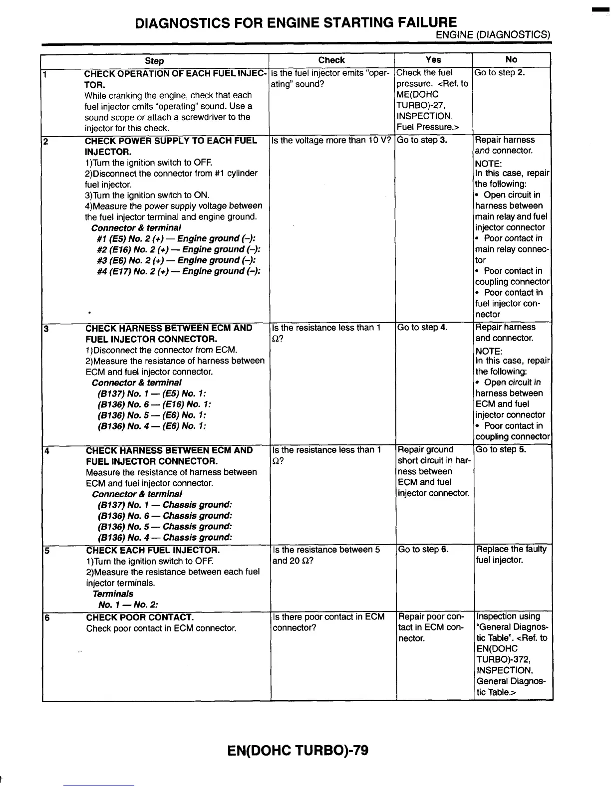
DIAGNOSTICS FOR ENGINE STARTING FAILURE
ENGINE (DIAGNOSTICS)
Step
CHECK OPERATION
OF
EACH FUEL INJEC-
TOR.
While cranking the engine, check that each
fuel injector emits “operating” sound. Use a
sound scope or attach a screwdriver
to the
injector for this check.
CHECK POWER SUPPLY TO EACH FUEL
INJECTOR.
1)Turn the ignition switch
to
OFF.
2)Disconnect the connector from
#I
cylinder
fuel injector.
3)Turn the ignition switch to ON.
4)Measure the power supply voltage between
the fuel injector terminal and engine ground.
#I
(€5)
No.
2
(+)
-
Engine ground
(-):
#2
(E 16)
No.
2
(+)
-
Engine ground
(-):
#3 (E6)
No.
2
(+)
-
Engine ground
(-):
#4
(El 7)
No.
2
(+)
-
Engine ground
(-):
Connector
&
terminal
I
CHECK HARNESS BETWEEN ECM AND
FUEL INJECTOR CONNECTOR.
1)Disconnect the connector from ECM.
2)Measure the resistance of harness between
ECM and fuel injector connector.
Connector
&
terminal
(8137)
NO.
1
-
(€5)
NO.
1:
(8136)
NO.
6
-
(€16)
NO.
1:
(8136)
NO.
5
-
(E6)
NO.
1:
(8136)
NO.
4
-
(€6)
NO.
1:
I
CHECK HARNESS BETWEEN ECM AND
FUEL INJECTOR CONNECTOR.
Measure the resistance of harness between
ECM and fuel injector connector.
Connector
&
terminal
(8137)
No.
1
-
Chassis ground:
(8136)
No.
6
-
Chassis ground:
(8136)
No.
5
-
Chassis ground:
(8136)
No.
4
-
Chassis ground:
P
CHECK EACH FUEL INJECTOR.
1)Turn the ignition switch to
OFF.
2)Measure the resistance between each fuel
injector terminals.
Terminals
NO.
1
-NO.
2:
i
CHECK
POOR
CONTACT.
Check poor contact in ECM connector.
~~~ ~~
Check
;
the fuel injector emits “oper-
iting” sound?
s
the voltage more than
10
V?
s
the resistance less than
1
2?
s
the resistance less than
1
A?
s
the resistance between
5
ind
20
Q?
s
there poor contact in ECM
:onnector?
Yes
;heck the fuel
bressure. <Ref.
to
AE(D0HC
NSPECTION,
-uel Pressure.>
20
to
step
3.
-URBO)-27,
30
to
step
4.
qepair ground
short circuit in har-
less between
ECM and fuel
njector connector.
So
to step
6.
Repair poor con-
tact in ECM con-
nector.
No
20
to
step
2.
3epair harness
ind connector.
qOTE:
n this case, repaii
he following:
1
Open circuit in
iarness between
nain relay and fuel
njector connector
1
Poor
contact in
nain relay connec,
:or
1
Poor contact in
:oupling connectol
1
Poor contact in
‘uel injector con-
lector
qepair harness
and connector.
MOTE:
in this case, repai
the following:
1
Open circuit in
iarness between
ECM
and fuel
njector connector
1
Poor contact in
:oupling connect0
So
to step
5.
Replace the faulty
fuel injector.
Inspection using
“General Diagnos-
tic Table”. <Ref.
to
EN(D0HC
TURBO)-372,
INSPECTION,
General Diagnos-
tic Table.>
EN(D0HC TURBO)-79