DIAGNOSTIC PROCEDURE WITH DIAGNOSTIC TROUBLE CODE (DTC)
ENGINE (DIAGNOSTICS)
Check
Step
I
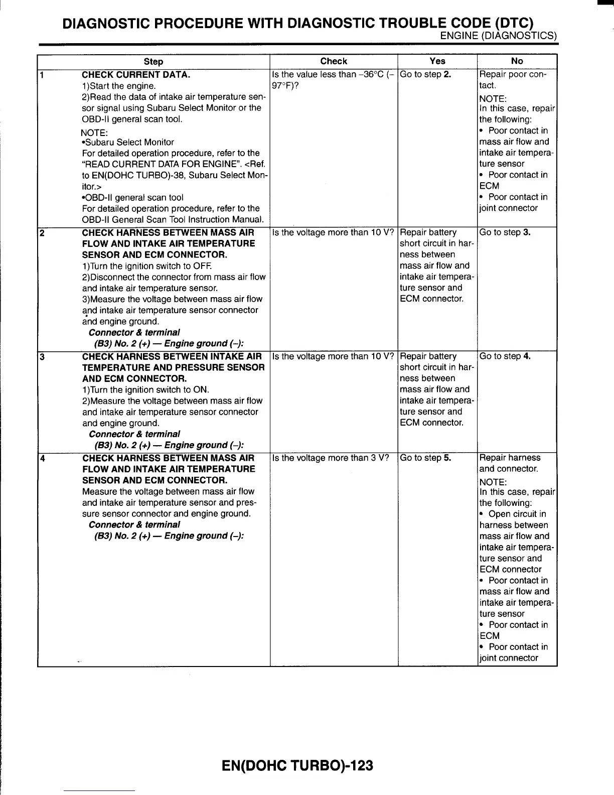
CHECK CURRENT DATA.
1)Start the engine.
2)Read the data of intake air temperature sen-
sor signal using Subaru Select Monitor or the
OBD-I1 general scan
tool.
NOTE:
*Subaru Select Monitor
For detailed operation procedure, refer
to
the
“READ CURRENT DATA FOR ENGINE”. <Ref.
to EN(D0HC TURBO)-38, Subaru Select Mom
itor.>
*OBD-ll general scan tool
For detailed operation procedure, refer
to
the
OBD-ll General Scan Tool Instruction Manual.
CHECK HARNESS BETWEEN MASS AIR
FLOW AND INTAKE AIR TEMPERATURE
SENSOR AND ECM CONNECTOR.
1)Turn the ignition switch to
OFF.
2)Disconnect the connector from mass air flow
and intake air temperature sensor.
3)Measure the voltage between mass air flow
?nd intake air temperature sensor connector
and engine ground.
!
Connector
&
terminal
(63)
No.
2
(+)
-
Engine ground
(-):
CHECK HARNESS BETWEEN INTAKE AIR
TEMPERATURE AND PRESSURE SENSOR
AND ECM CONNECTOR.
1)Turn the ignition switch
to ON.
2)Measure the voltage between mass air flow
and intake air temperature sensor connector
and engine ground.
I
Connector
&
terminal
(63)
No.
2
(+)
-
Engine ground
(-):
CHECK HARNESS BETWEEN MASS AIR
FLOW AND INTAKE AIR TEMPERATURE
SENSOR AND ECM CONNECTOR.
Measure the voltage between mass air flow
and intake air temperature sensor and pres-
sure sensor connector and engine ground.
(63)
No.
2
(+)
-
Engine ground
(-)I
I
Connector
&
terminal
Yes
17”F)?
;
the voltage more than 10
V?
s
the voltage more than 10
V?
s
the voltage more than 3
V?
No
Repair battery
short circuit in har-
ness between
mass air flow and
intake air tempera-
ture sensor and
ECM connector.
Repair battery
short circuit in har-
ness between
mass air flow and
intake air tempera-
ture sensor and
ECM connector.
Go
to
step
5.
Repair poor con-
tact.
NOTE:
In this case, repaii
the following:
Poor contact in
mass air flow and
intake air tempera-
ture sensor
*
Poor contact in
ECM
Poor contact in
ioint connector
Go
to
step
3.
Go to step
4.
Repair harness
and connector.
NOTE:
In this case, repaii
the following:
Open circuit in
harness between
mass air flow and
intake air tempera
ture sensor and
ECM connector
*
Poor contact in
mass air flow and
intake air tempera-
ture sensor
Poor contact in
ECM
Poor contact in
joint connector
EN(D0HC
TURBO)-123