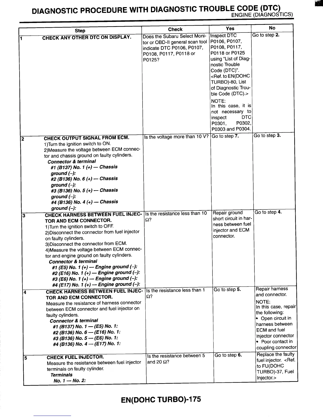
and connector.
NOTE:
In this case, rep?
the following:
Open circuit in
harness between
ECM and fuel
injector connect0
Poor contact in
coupling connect
Replace the faulty
fuel injector. <Ref.
to FU(D0HC
TURBO)-37, Fuel
Injector.>
Go
to step
6.
1
CHECK OUTPUT SIGNAL FROM ECM.
1)Turn the ignition switch to ON.
2)Measure the voltage between ECM connec-
tor and chassis ground on faulty cylinders.
Connector
&
terminal
#1
(6137)
No.
1
(+)
-
Chassis
ground
(-):
#2
(6136)
No,
6
(+)
-
Chassis
ground
(-):
#3 (8136)
No.
5
(+)
-
Chassis
ground
(-):
#4
(6136)
No.
4
(+)
-
Chassis
around
(-1:
Yes
Step
Check
No
CHECK ANY OTHER DTC ON DISPLAY.
Does the Subaru Select Moni-
tor or OBD-II general scan tool
indicate DTC P0106, P0107,
PO1 08, PO1 17, PO1 18 or
PO1 25?
3epair ground
;hort circuit in ha1
less between fue
njector and ECM
:onnector.
Inspect DTC
P0106, P0107,
P0108, P0117,
PO1 18 or PO1 25
using “List of Diag.
nostic Trouble
Go
to step
2.
Go
to step
5.
Is
the voltage more than
10
V?
;o
to step
3.
30
to step
4.
Repair harness
Code (DTC)”.
<Ref. to EN(D0HC
TURBO)-80, List
of Diagnostic Trou,
ble Code (DTC).>
NOTE:
In this case, it
i!
not necessary tc
inspect DT(
P0301, PO302
PO303 and PO304
Go
to step
7.
I
.,
CHECK HARNESS BETWEEN FUEL INJEC-
1)Turn the ignition switch to OFF.
2)Disconnect the connector from fuel injector
on faulty cylinders.
3)Disconnect the connector from ECM.
4)Measure the voltage between ECM connec-
tor and engine ground on faulty cylinders.
TOR AND ECM CONNECTOR.
Connector
&
terminal
#1
(€5)
No.
1
(+)
-
Engine ground
(-):
#2
(€16)
No.
1
(+)
-
Engine ground
(-):
#3 (E6)
No.
1
(+)
-
Engine ground
(-):
#4
(El 7)
No.
1
(+)
-
Engine ground
(-):
CHECK HARNESS BETWEEN FUEL INJEC-
TOR AND ECM CONNECTOR.
Measure the resistance of harness connector
between ECM connector and fuel injector on
faulty cylinders.
I
Connector
&
terminal
#1
(6137)
NO.
1
-(E5)
NO.
1:
#2
(8136)
NO.
6
-
(E16)
NO.
1:
#3 (8136)
NO.
5
-
(E6)
NO.
1:
#4
(6136)
NO.
4
-
(E17)
NO.
1:
5
CHECK FUEL INJECTOR.
Measure the resistance between fuel injector
terminals on faulty cylinder.
Terminals
NO.
1
-
NO.
2:
EN(D0HC
TURBO)-175
Is
the resistance less than
10
R?
Is
the resistance less than
1
Q?
Is
the resistance between 5
and 20
R?











 To Next Page