SunFounder ESP32 Starter Kit
•
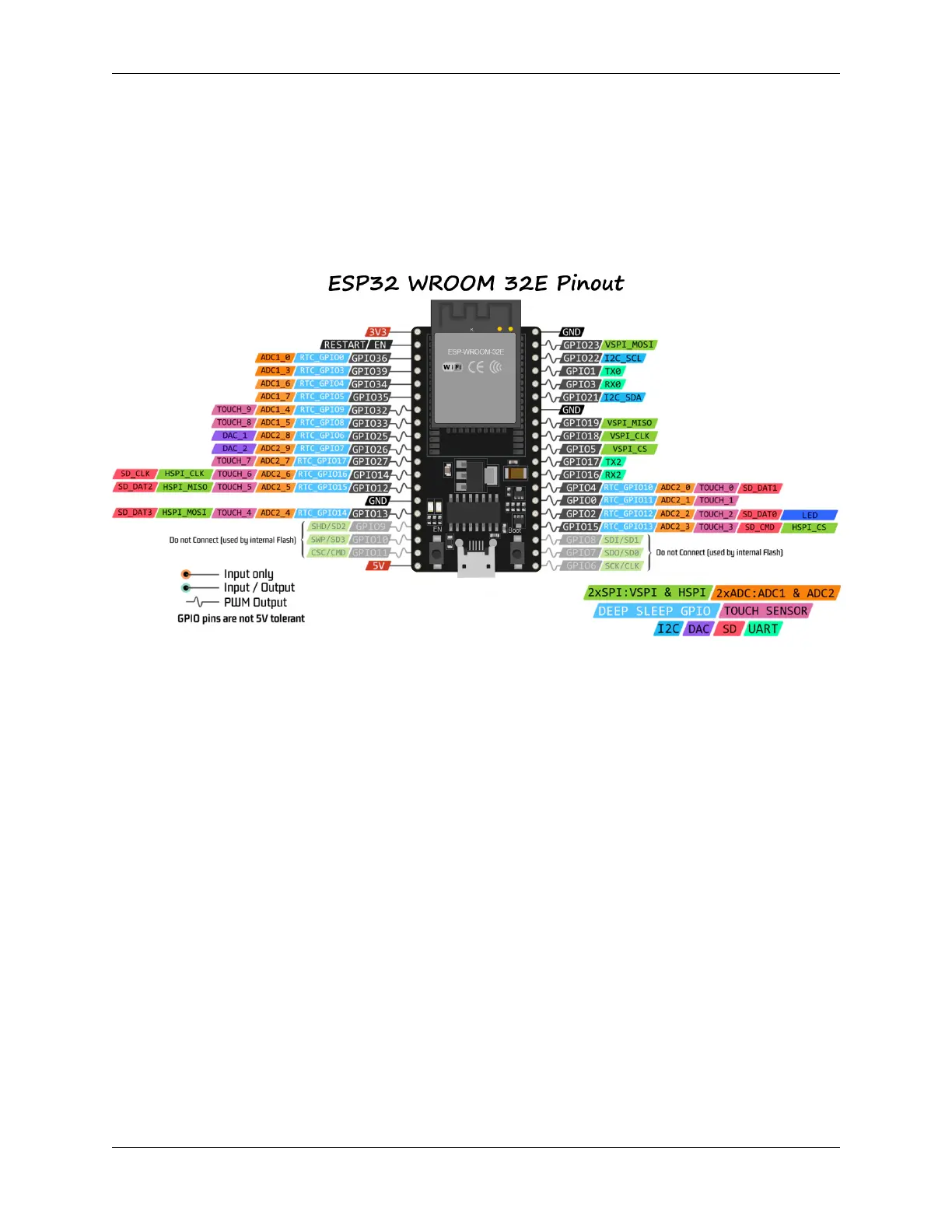
5.1.1 Pinout Diagram
The ESP32 has some pin usage limitations due to various functionalities sharing certain pins. When designing a project,
it’s a good practice to carefully plan the pin usage and cross-check for potential conflicts to ensure proper functioning
and avoid issues.
Here are some of the key restrictions and considerations:
• ADC1 and ADC2: ADC2 cannot be used when WiFi or Bluetooth is active. However, ADC1 can be used
without any restrictions.
• Bootstrapping Pins: GPIO0, GPIO2, GPIO5, GPIO12, and GPIO15 are used for bootstrapping during the boot
process. Care should be taken not to connect external components that could interfere with the boot process on
these pins.
• JTAG Pins: GPIO12, GPIO13, GPIO14, and GPIO15 can be used as JTAG pins for debugging purposes. If
JTAG debugging is not required, these pins can be used as regular GPIOs.
• Touch Pins: Some pins support touch functionalities. These pins should be used carefully if you intend to use
them for touch sensing.
• Power Pins: Some pins are reserved for power-related functions and should be used accordingly. For example,
avoid drawing excessive current from power supply pins like 3V3 and GND.
• Input-only Pins: Some pins are input-only and should not be used as outputs.
5.1. ESP32 WROOM 32E 681