SunFounder ESP32 Starter Kit
5.1.2 Strapping Pins
ESP32 has five strapping pins:
Strapping Pins Description
IO5 Defaults to pull-up, the voltage level of IO5 and IO15 affects the Timing of SDIO
Slave.
IO0 Defaults to pull-up, if pulled low, it enters download mode.
IO2 Defaults to pull-down, IO0 and IO2 will make ESP32 enter download mode.
IO12(MTDI) Defaults to pull-down, if pulled high, ESP32 will fail to boot up normally.
IO15(MTDO) Defaults to pull-up, if pulled low, debug log will not be visible. Additionally, the
voltage level of IO5 and IO15 affects the Timing of SDIO Slave.
Software can read the values of these five bits from register “GPIO_STRAPPING”. During the chip’s system reset
release (power-on-reset, RTC watchdog reset and brownout reset), the latches of the strapping pins sample the voltage
level as strapping bits of “0” or “1”, and hold these bits until the chip is powered down or shut down. The strapping
bits configure the device’s boot mode, the operating voltage of VDD_SDIO and other initial system settings.
Each strapping pin is connected to its internal pull-up/pull-down during the chip reset. Consequently, if a strapping pin
is unconnected or the connected external circuit is high-impedance, the internal weak pull-up/pull-down will determine
the default input level of the strapping pins.
To change the strapping bit values, users can apply the external pull-down/pull-up resistances, or use the host MCU’s
GPIOs to control the voltage level of these pins when powering on ESP32.
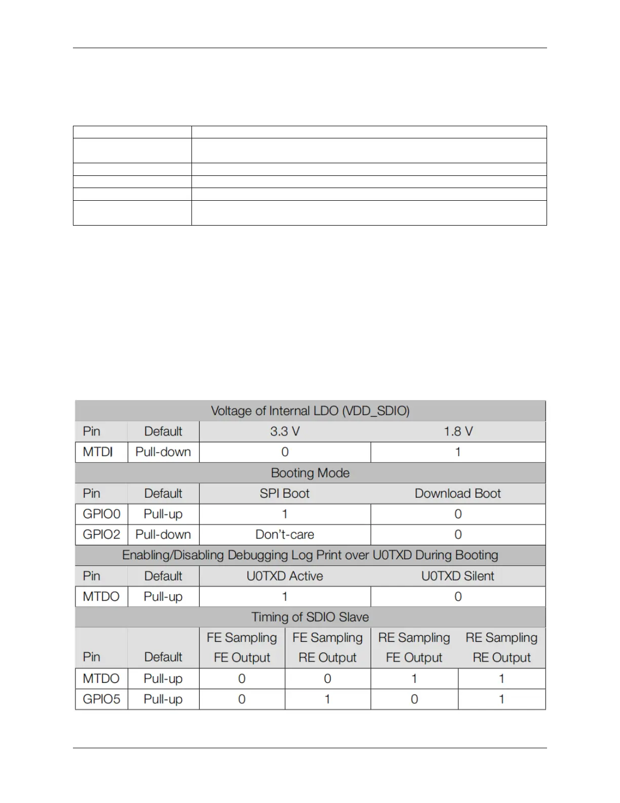
After reset release, the strapping pins work as normal-function pins. Refer to following table for a detailed boot-mode
configuration by strapping pins.
• FE: falling-edge, RE: rising-edge
682 Chapter 5. Learn about the Components in Your Kit