SunFounder ESP32 Starter Kit
COMPONENT INTRODUCTION PURCHASE LINK
ESP32 WROOM 32E
ESP32 Camera Extension -
Jumper Wires
Line Tracking Module
Available Pins
• Available Pins
Here is a list of available pins on the ESP32 board for this project.
Available Pins IO13, IO14, IO27, IO26, IO25, IO33, I35, I34, I39, I36, IO4, IO18, IO19,
IO21, IO22, IO23
• Strapping Pins (Input)
Strapping pins are a special set of pins that are used to determine specific boot modes during device
startup (i.e., power-on reset).
Strapping Pins IO5, IO0, IO2, IO12, IO15
Generally, it is not recommended to use them as input pins. If you wish to use these pins, consider
the potential impact on the booting process. For more details, please refer to the Strapping Pins
section.
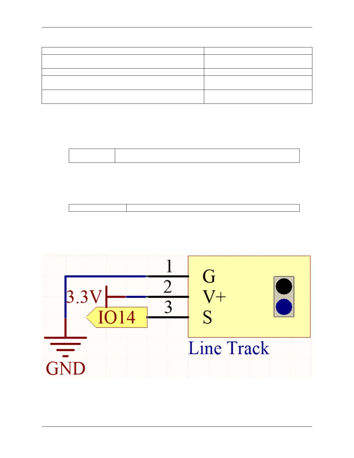
Schematic
When the line tracking module detects a black line, IO14 returns a high level. On the other hand, when it detects a
white line, IO14 returns a low level. You can adjust the blue potentiometer to modify the sensitivity of this module’s
detection.
Wiring
72 Chapter 1. For Arduino User