SunFounder ESP32 Starter Kit
Name ITEMS IN THIS KIT LINK
ESP32 Starter Kit 320+
You can also buy them separately from the links below.
COMPONENT INTRODUCTION PURCHASE LINK
ESP32 WROOM 32E
ESP32 Camera Extension -
Breadboard
Jumper Wires
Resistor
LED
Button
Transistor
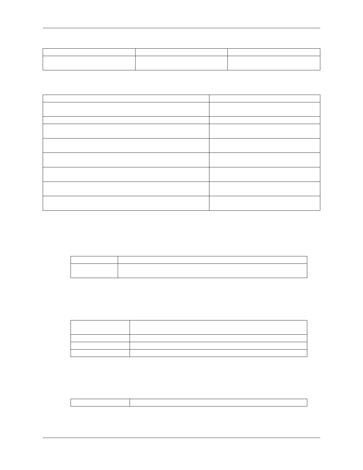
Available Pins
• Available Pins
Here is a list of available pins on the ESP32 board for this project.
For Input IO14, IO25, I35, I34, I39, I36, IO18, IO19, IO21, IO22, IO23
For Output IO13, IO12, IO14, IO27, IO26, IO25, IO33, IO32, IO15, IO2, IO0, IO4, IO5,
IO18, IO19, IO21, IO22, IO23
• Conditional Usage Pins (Input)
The following pins have built-in pull-up or pull-down resistors, so external resistors are not required
when using them as input pins:
Conditional Usage
Pins
Description
IO13, IO15, IO2, IO4 Pulling up with a 47K resistor defaults the value to high.
IO27, IO26, IO33 Pulling up with a 4.7K resistor defaults the value to high.
IO32 Pulling down with a 1K resistor defaults the value to low.
• Strapping Pins (Input)
Strapping pins are a special set of pins that are used to determine specific boot modes during device
startup (i.e., power-on reset).
Strapping Pins IO5, IO0, IO2, IO12, IO15
Generally, it is not recommended to use them as input pins. If you wish to use these pins, consider
the potential impact on the booting process. For more details, please refer to the Strapping Pins
78 Chapter 1. For Arduino User