10 Appendix II: LCD Operation User Manual
92
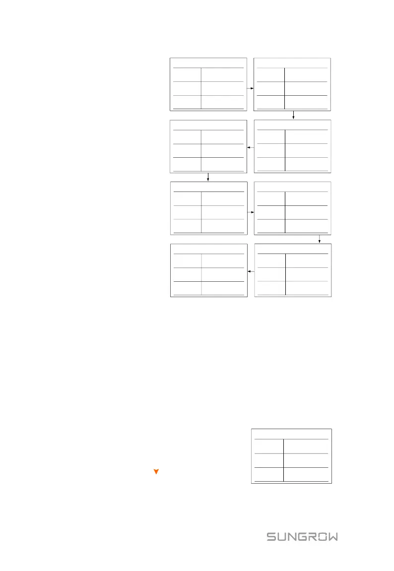
(1) 81>.S1: over-frequency
test (stage I)
(2) 81<.S1:
under-frequency test
(stage I)
(3) 59.S1: over-voltage test
(stage I)
(4) 27.S1: under-voltage
test (stage I)
(5) 81>.S2: over-frequency
test (stage II)
(6) 81<.S2:
under-frequency test
(stage II)
(7) 59.S2: over-voltage test
(stage II)
(8) 27.S2: under-voltage
test (stage II)
Imp.: the default protection
threshold
Ril.: the actual sample value
81>.S1
Imp.
Ril.
Risult.
50.50 Hz
49.99 Hz
Test...
59.S1
Imp.
Ril.
Risult.
253.0 V
230.0 V
Test...
81<.S1
Imp.
Ril.
Risult.
49.50 Hz
49.99 Hz
Test...
27.S1
Imp.
Ril.
Risult.
195.5 V
230.0 V
Test...
81>.S2
Imp.
Ril.
Risult.
51.50 Hz
49.99 Hz
Test...
59.S2
Imp.
Ril.
Risult.
264.5 V
230.0 V
Test...
81<.S2
Imp.
Ril.
Risult.
47.50 Hz
49.99 Hz
Test...
27.S2
Imp.
Ril.
Risult.
92.0 V
230.0 V
Test...
For over- frequency / voltage protection testing, the default protection
threshold (Imp.) is linearly decreased with a ramp <= 0.05 Hz/s or <= 0.05
Vn/s. The protection function will be triggered if the threshold is lower than
the actual sample value (Ril.).
For under- frequency / voltage protection testing, the default protection
threshold (Imp.) is linearly increased with a ramp <= 0.05 Hz/s or <= 0.05
Vn/s. The protection function will be triggered if the threshold is higher
than the actual sample value (Ril.).
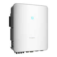
If the protection function is triggered, the LED
indicator will be lit red and the corresponding
error code will be displayed on the main screen.
When the test is completed, the interface as
shown will appear. Press to view the test
result and the trip time.
Completa!
Imp.
Ril.
Risult.
0.0 V
0.0 V
Pass.