POWER UNIT 6-23
Valve seating contact width
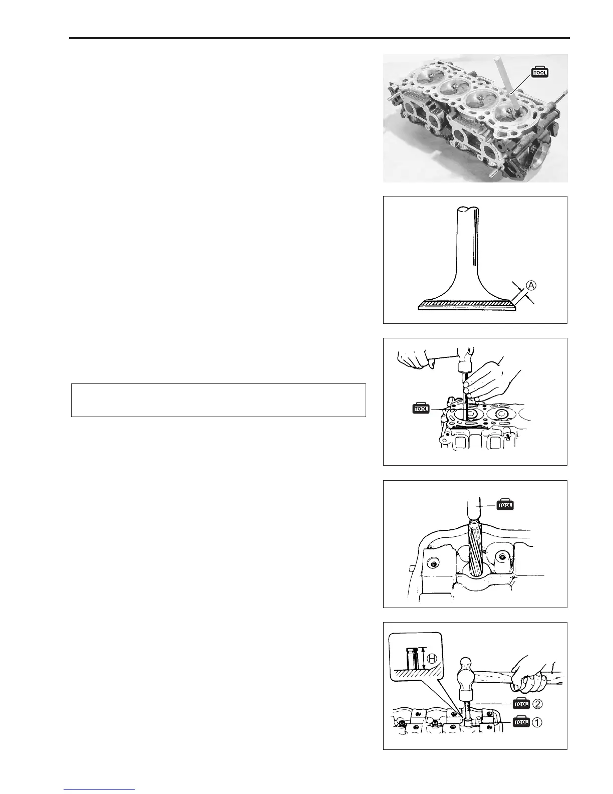
Measure the valve seating contact width A as follows:
1. Coat the valve seat evenly with Prussian blue (or equivalent).
2. Install the valve into the valve guide.
3. Put the valve lapper on the valve.
$ 09916-10911: Valve lapper
4. Rotate the valve while gently tapping the valve contact area
against the seat.
5. Continuously pattern on the valve seating face with Prus-
sian blue.
6. Measure the valve seating contact width A.
$ 09900-20102: Vernier calipers
Standard: IN & EX 1.3 – 1.5 mm (0.05 – 0.06 in)
If the measurement is out of the specification, service the valve
seat.
NOTE:
For the valve seat servicing, see the “VALVE SEAT SERVICING”
section on the page 6-24.
VALVE GUIDE REPLACEMENT
!
Be careful not to damage the cylinder head when re-
placing the valve guide.
1. Drive the valve guide out toward the valve spring side.
$ 09916-44511: Valve guide remover / installer
3. Drive in the valve guide until the tool 1 contacts the cylin-
der head.
$ 09917-88210: Valve guide installer attachment – 1
09916-57321: Valve guide installer – 2
4. Measure the valve guide protrusion H.
$ 09900-20102: Vernier calipers
Valve guide protrusion:
Standard: IN & EX 14.0 mm (0.55 in)
2. Refinish the valve guide hole.
$ 09916-37310: Valve guide reamer (
φφ
φφ
φ12 mm)
09916-34542: Valve guide reamer handle
NOTE:
Turn the reamer clockwise, never counterclockwise.



 To Next Page