8-20 POWER TRIM AND TILT
PRINCIPLES OF OPERATION
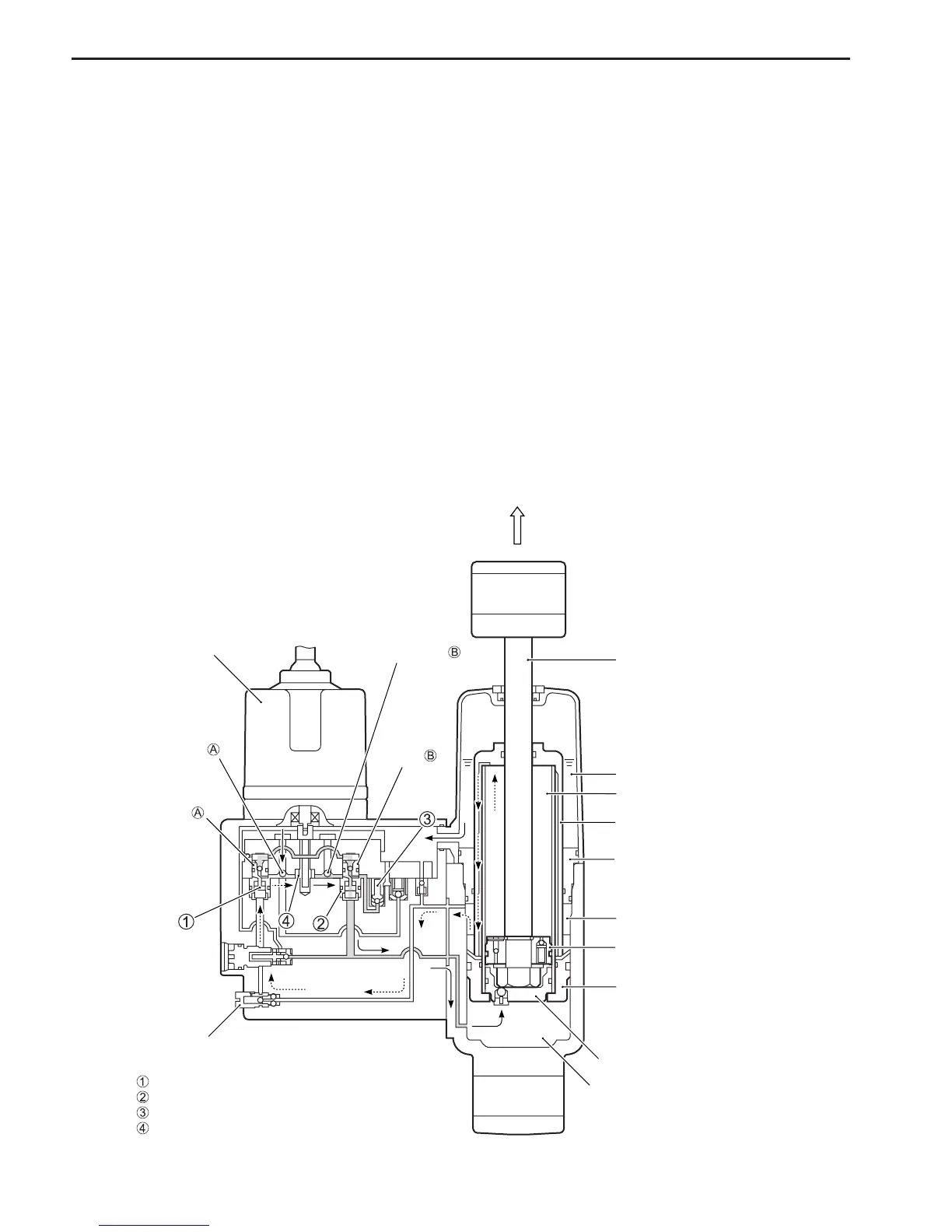
TRIM/TILT “UP” CIRCUIT
When the PTT switch is operated “UP” position, the electric motor and gear pump 4 will operation on clock-
wise direction.
Pressurized oil will open check valve A, oil will flow from reservoir to spool valve A via pump and spool valve
B.
The spool valve A will down, then “DOWN” pressure main check valve 1 will open.
Oil in the upper chamber will return to pump via 2-way valve, and then oil pressure will rise and open “UP”
pressure main check valve 2, then oil will flow to lower cylinder chamber of cylinder.
It makes the piston rod push up and the engine tilt up.
To keep oil level, oil flows from reservoir to pump through the check valve A.
Oil through the “DOWN” pressure main check valve 1 and returns to pump.
When trim motor stops, both the “DOWN” pressure main check valve 1 and the “UP” pressure main check
valve 2 will close to retain tilt/trim position.
In the trim area, trim piston and floating tube are moving with piston rod.
When full trim/tilt “UP” position is attained, sustained operation of the “UP” relay will have no effect, as pump
oil flow will be returned to the reservoir through the “UP” relief valve 3.
Tilt rod
Oil reservoir
Tilt cylinder upper chamber
Floating tube
Trim cylinder upper chamber
Tilt piston
Trim piston
Free piston
Lower cylinder chamber
2-way valve
PTT motor
“DOWN” pressure main check valve
“UP” pressure main check valve
“UP” relief valve
Gear pump
End case
Check valve
Check valve
Spool valve
Spool
valve