ENGINE CONTROL SYSTEM 3-39
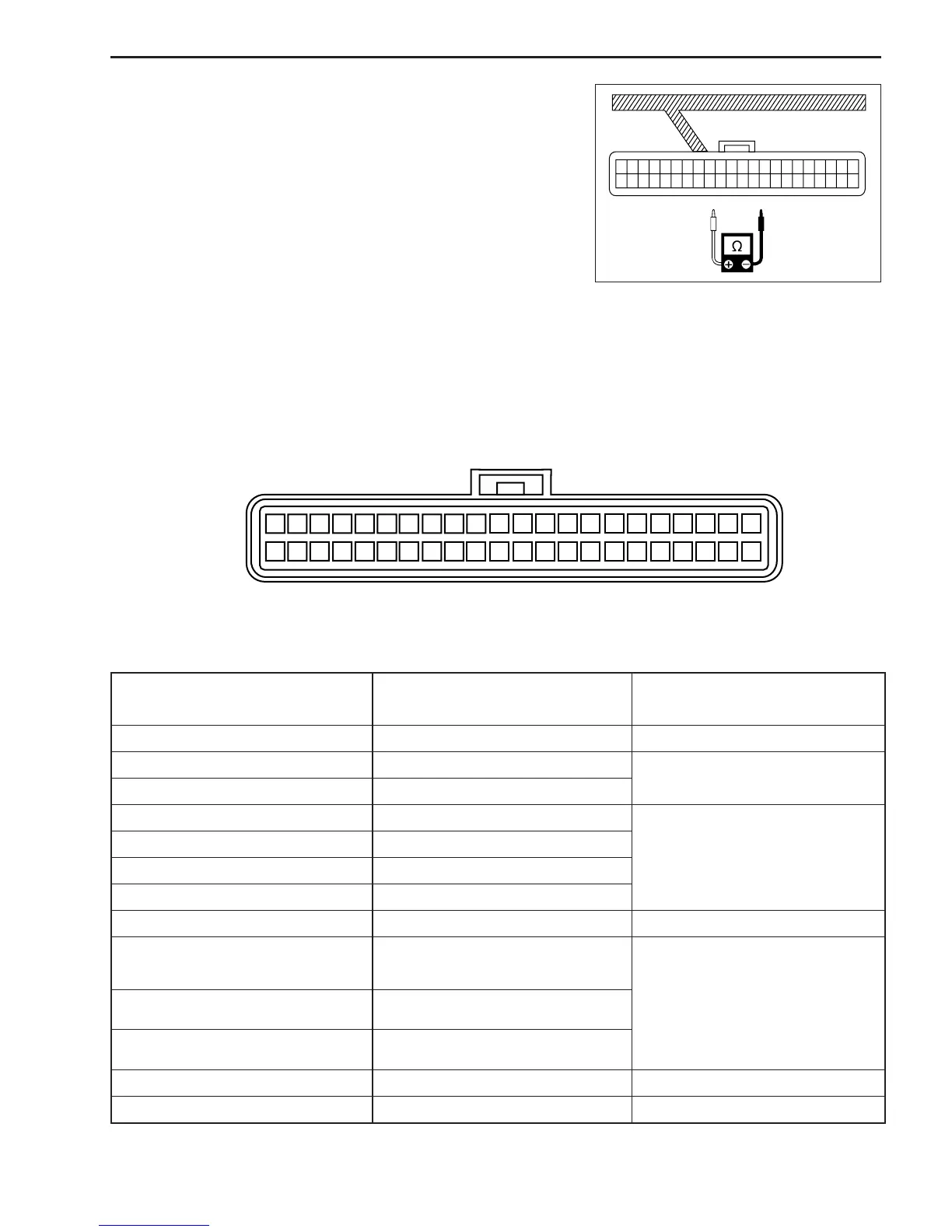
22 21 20 19 18 17 16 15 14 13 12 11 10 9 8 7 6 5 4 3 2 1
44 43 42 41 40 39 38 37 36 35 34 33 32 31 30 29 28 27 26 25 24 23
INSPECTION FOR RESISTANCE
# 09930-99320: Digital tester
& Tester range:
ΩΩ
ΩΩ
Ω (Resistance)
NOTE:
Make sure that the ignition switch is always OFF when measur-
ing resistance.
1. Disconnect the battery cables from the battery.
2. Disconnect the wire harness from the ECM.
3. Connect the tester probes to the terminal of the wire harness
side, and measure resistance according to the “RESISTANCE
TABLE”.
TERMINAL LAYOUT OF WIRE HARNESS CONNECTOR
RESISTANCE TABLE
ITEM
TERMINAL NO. FOR TESTER
PROBE CONNECTION
STANDARD RESISTANCE
(at 20°C)
CMP sensor 15 to 11
Ignition coil No.1 & 4 (Primary) 44 to 30
Ignition coil No.2 & 3 (Primary) 43 to 30
Fuel injector No.1
Fuel injector No.2
Fuel injector No.3
IAC valve
Cylinder temperature sensor
Exhaust manifold temp. sensor
7 to 11
ECM main relay 13 to Terminal A [NOTE 1]
Starter motor relay 5 to GND [NOTE 2]
40 to 30
39 to 30
18 to 30
38 to 30
9 to 11
31 to 11
168 – 252 Ω
1.9 – 2.5 Ω
11.0 – 16.5 Ω
4.8 – 7.2 Ω
0°C ( 32°F) : 5.3 – 6.6 kΩ
25°C ( 77°F) : 1.8 – 2.3 kΩ
50°C (122°F) : 0.73 – 0.96 kΩ
75°C (135°F) : 0.33 – 0.45 kΩ
(Thermistor characteristic)
145 – 190 Ω
3.5 – 5.1 Ω
IAT sensor
Fuel injector No.4 22 to 30