XLi Time & Frequency System 189
XLi-man, Issue 8, 6/17/2008, Rev. H
2
5
1
SSSSSSSSSSSS SSSSSSSSSS SSSSSSS S SSS S SSSSS S
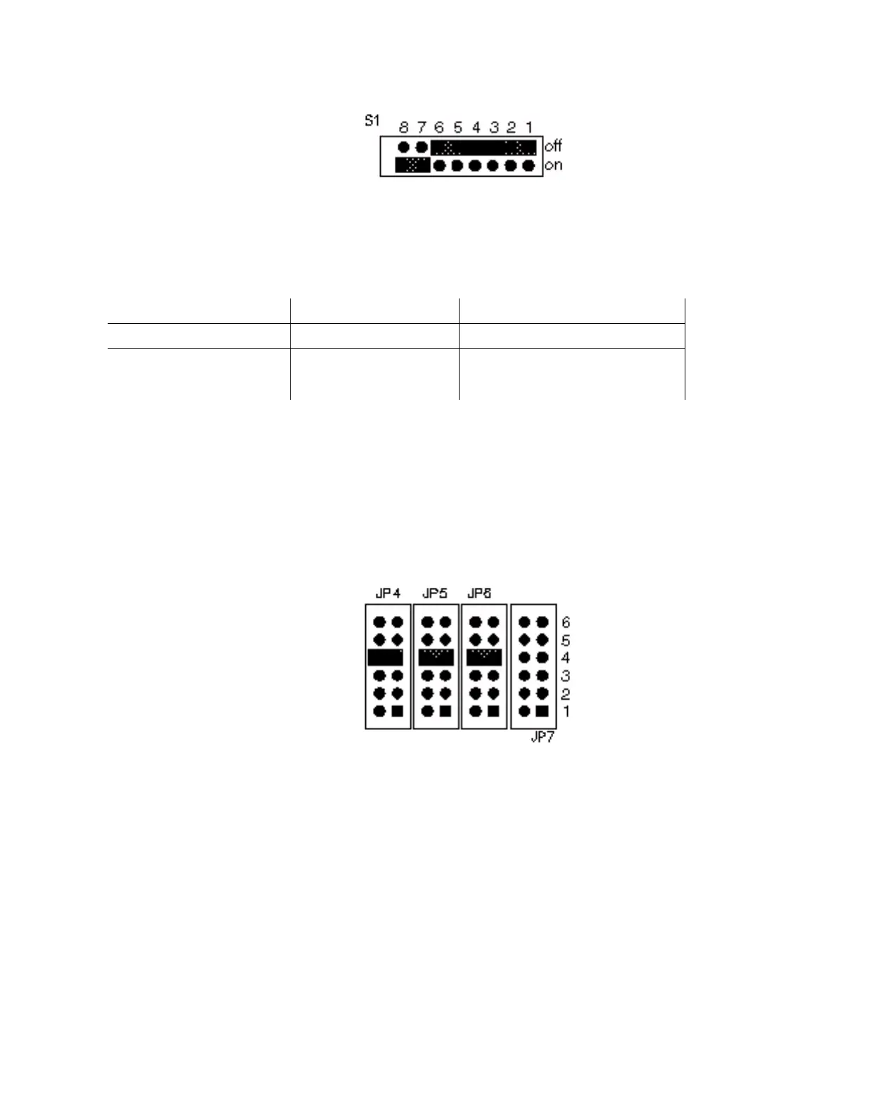
Figure 17:S1 has eight dip switch positions. (Lettering inverted for this illustration.)
To configure the card’s settings, refer to the following tables:
E1 Output Wave Shaping: The E1 doesn’t require output wave shaping BECAUSE.
E1 AIS Assertion and Output Signal Control on Major Fault:
Figure 18:JP 4, JP5, JP6, and JP7 (Positions numbered 1-6 for this illustration.)
E1 Output A E1 Output B
S1 Position 1234567
Do not use ONONONONONONON
CEPT G.703 XXXXXXX
'X' means that the setting is unimportant, except that for either output, all ON is not allowed.
Assert AIS and Turn Off Outputs: S1 Position 8 OFF
No AIS and Leave Outputs On: S1 Position 8 ON (Default)
Artisan Technology Group - Quality Instrumentation ... Guaranteed | (888) 88-SOURCE | www.artisantg.com

 Loading...