XLi Time & Frequency System 23
XLi-man, Issue 8, 6/17/2008, Rev. H
2
5
1
SSSSSSSSSSSS SSSSSSSSSS SSSSSSS S SSS S SSSSS S
Making Additional Connections
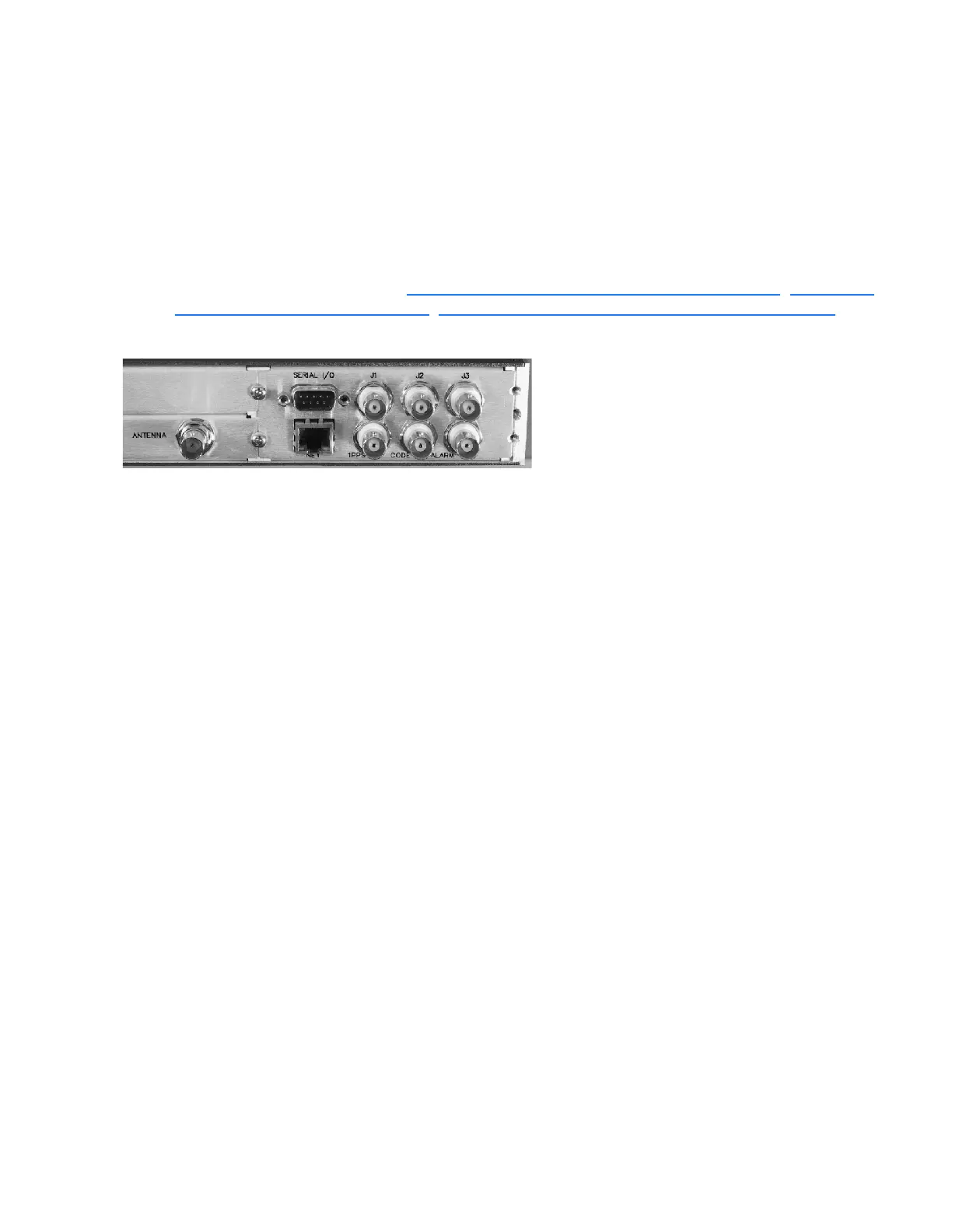
Make the following optional connections to the standard input/output connectors on the XLi back panel:
• The ANTENNA connector to a GPS antenna cable. (Note: Use a 12-volt capable GPS antenna.)
• The NET network port (RJ-45) to an ethernet network using Cat 5 cable (supplied). This
connection is needed to manage the XLi remotely, or to use the optional NTP function.
• The SERIAL I/O connector to a PC using the supplied RS-232 null modem cable.
• J1, J2, and J3, if needed. See “F110 – J1 Input (Time Code, TIET)” on page 137
, “F111 – J2
Output (Rate, PPO)” on page 142, “F113 – J3 Input (Aux Ref, Freq Meas)” on page 146
.
Figure 5: Connectors: ANTENNA, SERIAL I/O, J1, J2, J3, NET, 1PPS, CODE, ALARM
Connecting the Power Supply
Warning: Ensure that a disconnect device, such as a switch, with the appropriate voltage/
current rating is provided when operating/installing the XLi.
Connect the Power Supply it to a power source. The green STATUS light indicates that the XLi is
receiving power.
Notes for optional DC power supplies:
• Use a 15 amp circuit breaker in series with the DC power source; avoid connecting directly to a
DC power source without the breaker.
• 14 gage wire is the minimum recommended for DC power source hookup.
• DC Power Supply Only to be used in a restricted access area.
• The screw torque range on the Power Terminal Block is 5 to 8 inch pounds.
• When connecting to a DC power source, first connect the positive power cable to “+” on the
power supply, then connect the negative power supply cable to “−”.
Upon receiving power, the XLi goes through its startup sequence; displaying “BOOTING”, “LOADING”,
and “STARTING”. After approximately 40 seconds, the XLi displays the clock status, and user interfaces
(front panel/command line) become available.
Artisan Technology Group - Quality Instrumentation ... Guaranteed | (888) 88-SOURCE | www.artisantg.com

 Loading...