20 XLi Time & Frequency System
XLi-man, Issue 8, 6/17/2008, Rev. H
SSSSSSSSSSSS SSSSSSSSSS SSSSSSS S SSS S SSSSS S
1
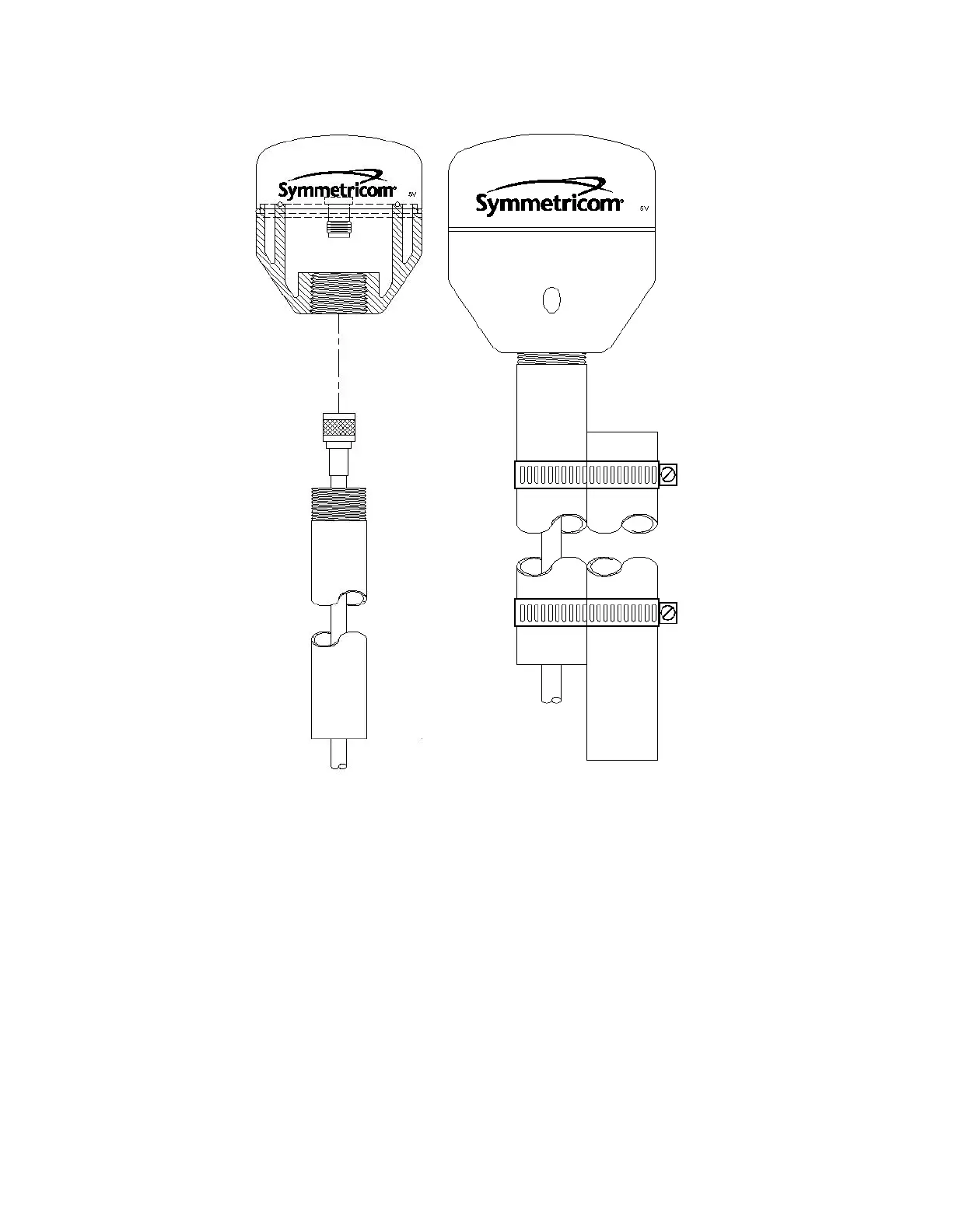
Figure 3: L1 GPS Antenna - methods for cabling and mounting
Connecting the Antenna to the Receiver
Note that the pipe in the left image of Figure 3 does not separate from the antenna as shown. It is shown
in this image for conceptual purposes.
The antenna itself is mounted inside the top half of white antenna assembly. In the image above, this
part has the Symmetricom logo on it and the dotted line with the TNC signal connector below it. The top
half of the antenna housing is sealed and therefore weather-proof.
The lower part of the white antenna housing shown above, below the dotted line, is used for support and
for protecting the antenna cable connection. The two halves of the white antenna housing are secured
together by four 4-40 UNC captive screws. The two antenna housing halves come together with an O-
Artisan Technology Group - Quality Instrumentation ... Guaranteed | (888) 88-SOURCE | www.artisantg.com

 Loading...