202 XLi Time & Frequency System
XLi-man, Issue 8, 6/17/2008, Rev. H
SSSSSSSSSSSS SSSSSSSSSS SSSSSSS S SSS S SSSSS S
1
estimate of the time error, and three data valid strobes. The data and strobes are provided by combining
the signals from two connectors.
OUTPUT
Day-of-year, time quality flags, 1PPS strobe and 1kPPS strobe.
Outputs (TTL): LVTTL Levels, 4mA source or sink
Logic Low < 0.4 V
Logic High > 2.4 V
Qty: 1
Connector: Panel-mounted female 50-pin D and 25-pin D connector
Physical: Double high option bay
CPU-Aware: Yes
Compatibility Legacy XL-DC Parallel BCD Millisecond Module (86-390-1)
1 PPS STROBE: This line goes to the high state between the second and 100 ns after the second. It
remains high for 500 ms.
1 kPPS STROBE: This line goes to the high state between the millisecond and 100 ns after the
millisecond strobe. It remains high for 500 us.
1 MPPS STROBE: This line goes to the high state between the microsecond and 100 ns after the
microsecond strobe. It remains high for 500 ns.
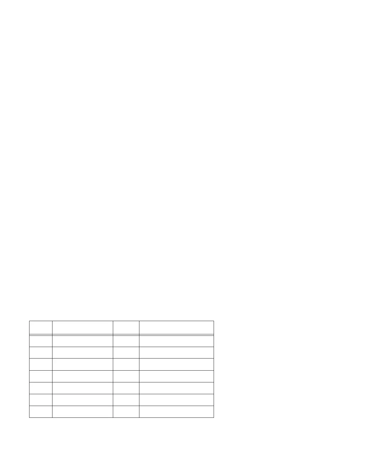
50-pin D MILLISECONDS CONNECTOR PIN ASSIGNMENT
Table 6:
IN # OUTPUT PIN # OUTPUT
1 Ground 26 10’s of min
2 Not used 27 8’s of min
3 200’s of days 28 4’s of min
4 100’s of days 29 2’s of min
5 80’s of days 30 1’s of min
6 40’s of days 31 40’s of sec
7 20’s of days 32 20’s of sec
Artisan Technology Group - Quality Instrumentation ... Guaranteed | (888) 88-SOURCE | www.artisantg.com

 Loading...