21
3. Making connections
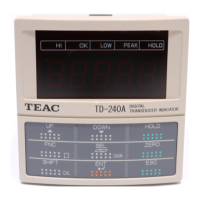
Connecting TEDS sensors and 4-wire sensors
Strain gauge transducer TD-9000T
A
B
C
D
-EXC (C)
+EXC (A)
-SIG (B)
+SIG (D)
SHIELD (E)
TEDS
GND
Teds Data
Memory
If not using the TEDS function, terminals 1 and 2 can be left
open.
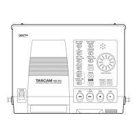
Connecting using 6 wires
Strain gauge transducer TD-9000T
-EXC (C)
+EXC (A)
-SIG (B)
+SIG (D)
SHIELD (E)
+SENS (F)
-SENS (G)
A
B
C
D
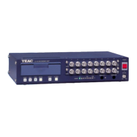
Usable sensor characteristics
o Output between +SIG and −SIG: ±3.2mV/V or less
o Voltage (current) between +EXC and −EXC: 10V DC, 5V DC
or 2.5V DC ±10% (30mA maximum current)
ATTENTION
Do not connect sensors that do not meet the rated output
(output between +SIG and −SIG) and the maximum safe exci-
tation voltage (voltage between +EXC and −EXC) specifications.
The wire colors are those that we use in the strain gauge trans-
ducers that we make.
Terminal
number
Signal Wire color
1 TEDS Orange
2 GND Green
3 +EXC (A) Red
4 +SENS (F) −
5 −SIG (B) Black
6 −EXC (C) Blue
7 −SENS(G) −
8 +SIG (D) White
9 SHIELD (E) Yellow
3-3. Displacement sensor
Power is only output (voltage or pulse) for the displacement
sensor selected with INPUT MODE on the DISPLACE. SENSOR
settings screen (page41).
+12V is output when voltage is selected, and +5V is output
when pulse is selected.
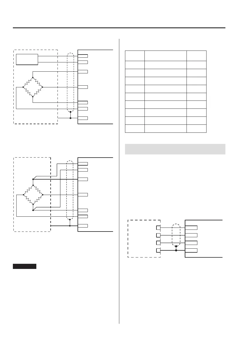
Displacement sensor (voltage)
The +12V power supply of pin 10 can be used as a 250mA
(maximum) power supply for an displacement sensor (voltage).
Connection example
Displacement sensor TD-9000T
GND
SHIELD
+12V OUT
STROKE IN
COM(GND)
F.G
+12V
OUT

 Loading...