22
3-3-1. Displacement sensor (pulse)
Connect a differential square wave output type displacement
sensor.
This unit internally converts differential output signals from
sensors (RS422 level) to TTL level.
o The +5V power supply of pin 17 can be used as a 500mA
(maximum) power supply for a displacement sensor (pulse).
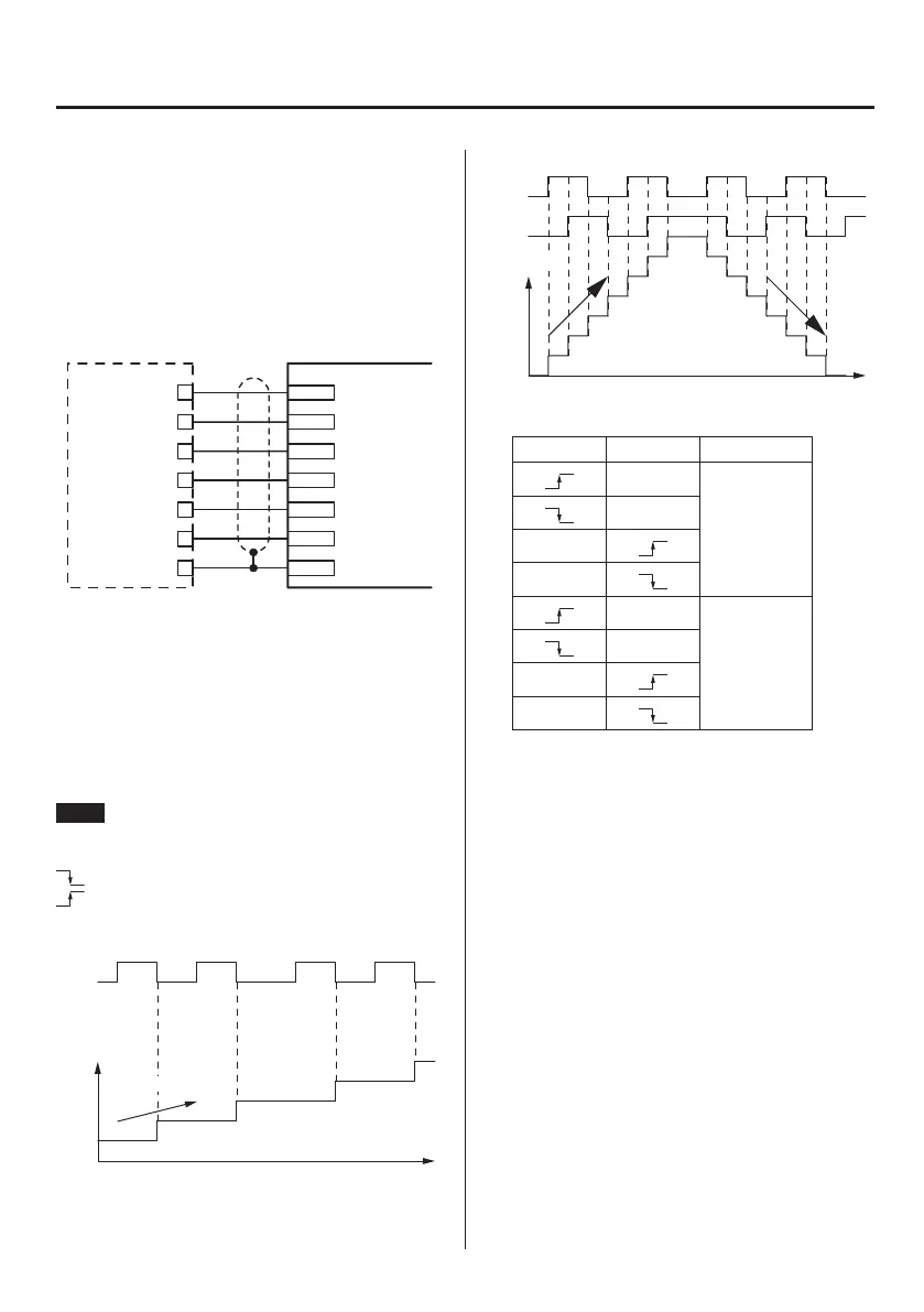
Connection example
Displacement sensor TD-9000T
(+)
SHIELD
(+)
(–)
(–)
+5V OUT
GND
+
–
+
–
COM(GND)
F.G
+5V
A phase
B phase
Power
supply
3-3-2. Displacement sensor (pulse)
counting method
The TD-9000T has modes that support A phase only and AB
phase (2-phase) output signals from displacement sensors
(pulse).
The count value changes as shown below for A phase only and
AB phase output.
NOTE
HI: Input is OFF
LO: Input is ON
: Changing from HI to LO
: Changing from LO to HI
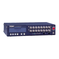
When output phase A
A phase
Count
Time
Up count
Up counts occur when the A phase input pulse signal is ON (at
the falling edge).
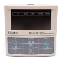
When output phase AB
A phase
B phase
Count
Time
Up
count
Down
count
Count operations
A phase input B phase input Count operation
LO
Up count
HI
HI
LO
HI
Down count
LO
LO
HI
Counts occur at both the rising and falling edges of A and B
phase input pulses.
See “Count operations” above for whether the count is up or
down.
3. Making connections