23
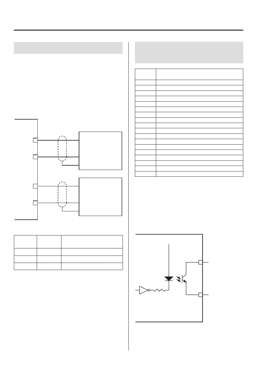
3-4. D/A Converter
For voltage output, connect an external device with a load
resistance of 2kΩ or more to V-OUT and COM.
For current output, connect an external device with a load
resistance, including cable wiring resistance, of 350Ω or less to
I-OUT and COM.
o Voltage output or current output can be used. They cannot
output both at the same time. Set voltage or current in the
D/A output setting of the sensor screen (page29).
TD-9000T
+
V
COM
+
I
COM
Shield
Shield
External device
Load resistance
2 kΩ or higher
+
−
+
−
GND
GND
External device
Load resistance
350 Ω or less
Terminal
number
Signal Explanation
14 V-OUT D/A voltage output
15 I-OUT D/A current output
16 COM D/A output common terminal
o The D/A output is isolated from this unit’s circuits.
3. Making connections
3-5. Control signal output terminals
(CONTROL connector)
Terminal
number
Signal
1 COM signal
2 COM signal
3 Unit error
4 Load cell error
5 Measurement complete
6 Trigger output 2
7 Trigger output 1
8 Band judgment output (load HI)
9 Band judgment output (load OK)
10 Band judgment output (load LO)
11 Judgment output (displacement HI)
12 Judgment output (displacement OK)
13 Judgment output (displacement LO)
14 Judgment output (load HH)
15 Judgment output (load HI)
16 Judgment output (load OK)
17 Judgment output (load LO)
18 Judgment output (load LL)
o The judgment output is isolated from this unit’s circuits by
a photocoupler.
3-5-1. Connecting control output
terminals
Open collector output (NPN, current sync)
20mA/30V maximum collector current
+5V
Judgment output
COM 1–2
Outputs 3–18
Maximum
20mA/30V
o For the operation of each signal, see “4-6. Start/stop mea-
surement” on page54.

 Loading...