44 1670 001-GB-I
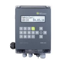
HDA eco
3
Content
1
Safety instructions ............................................................................................................ 6
2
Technical description ........................................................................................................ 8
2.1 Intended use ........................................................................................................................ 8
2.2 Description ........................................................................................................................... 8
2.3 Versions ................................................................................................................................ 8
2.4 Technical Data ..................................................................................................................... 9
2.5 Interfaces of the HDA eco ................................................................................................ 9
2.5.1 Interface flow meter ........................................................................................ 9
2.5.2 Interface level control ................................................................................... 11
2.5.3 Interface nozzle switch ................................................................................. 12
2.5.4 Interface pump motor ................................................................................... 13
2.6 Accessories ........................................................................................................................ 14
2.6.1 Software connection ...................................................................................... 15
2.6.1.1 mytecalemit Cloud............................................................................... 15
3
Assembly Instructions .................................................................................................... 16
3.1 Electric connection........................................................................................................... 16
3.1.1 Notes concerning electrical connection .................................................... 20
3.1.1.1 Relay Contact ........................................................................................ 20
3.1.1.2 Emergency mode switch .................................................................... 20
3.1.1.3 Battery Exchange ................................................................................ 21
3.1.1.4 Socket Modem ...................................................................................... 21
3.1.1.5 Float Switch .......................................................................................... 21
3.1.1.6 Cable Shielding ..................................................................................... 21
3.1.2 Installation of the float switch .................................................................... 21
3.1.3 Installation of the level probe (Optional) ................................................. 21
3.1.4 Retrofitting the level probe interface ....................................................... 23
3.1.5 Connection of the RS232 / RS422 interface ............................................ 23
3.1.5.1 RS232-connection ............................................................................... 23
3.1.5.2 Printer connection ............................................................................... 24
3.1.5.3 RS422-Connection ............................................................................... 25
3.1.5.4 LAN Connection .................................................................................... 25
3.1.5.5 WLAN connection ................................................................................ 26
3.1.5.6 CMR-connection ................................................................................... 27
3.1.5.7 Retrofitting the Data Interface ......................................................... 27
3.2 Calibration of the measuring system .......................................................................... 28
4
First steps – HDA eco...................................................................................................... 29
5
Operating of the Fluid Inventory Control System HDA eco .................................... 30
5.1 Switching on ...................................................................................................................... 30
5.1.1 Entry of values ................................................................................................ 30
5.2 Refuelling mode ................................................................................................................ 30
5.2.1 Driver identification (optional) ................................................................... 31
5.2.1.1 Vehicle identification (optional) ...................................................... 31
5.2.1.2 Tank content display (optional) ....................................................... 32
5.2.1.3 Software version display................................................................... 32
5.2.2 Dispensing without entering a code (optional) ....................................... 32
5.2.3 Entering the Odometer reading (optional) ............................................... 33
5.2.4 Entering the order number (optional) ....................................................... 33
5.2.5 Refuelling.......................................................................................................... 33
5.2.5.1 Entry of a preselected quantity ....................................................... 33
5.2.6 Refuelling procedure ..................................................................................... 34