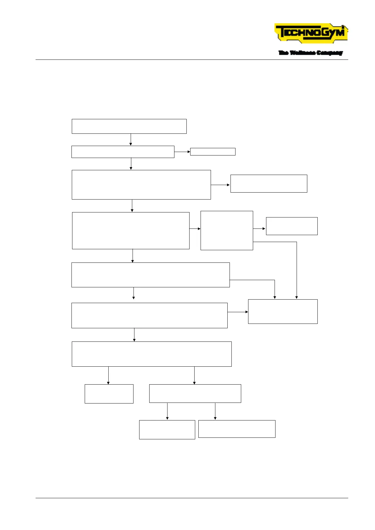
6.9 ANIMATION ON THE DISPLAY OF
DISCONNECTED EMERGENCY, WITH THE
INDICATION TO RE-CONNECT THE EMERGENCY
Emergency disconnected shown on the display, with
the indication to reconnect the emergency [**]
Reinsert the emergency correctly in its housing.
Problem solved*?
OK. Problem Solved.
YES
Disconnect patch connector no. 3A that connects the emergency
stop cable to the High Kit-Low Kit connection cable 0WCU1266xx.
Insert the tips of the tester between PIN 1 and PIN 2 of the
emergency stop cable 0WCU1266xx.
Is there continuity if the emergency stop is inserted? [1]
Replace the emergency stop cable
and/or the emergency stop unit.
Make sure the problem is solved.*
NO
NO
Check the alarm signal. Reconnect the connectors
that were previously disconnected.
Turn off the equipment. Insert the tips of the tester
between pin 2 of patch connector no. 6 and the earth.
Turn on the equipment.
Is 12V present and does it remain high?[4]
YES
Replace the display, [2].
Make sure the problem
is solved.*
NO
Disconnect the connector of the High Kit-Low Kit connection cable
0WCU1266xx connected to the CPU. Measure the continuity between
PIN 1 of patch connector no. 3A and PIN 15 of the cable display
connector 0WCU1266xx. Is there continuity? [5]
YES
Replace the High Kit-Low Kit
connection cable 0WCU1266xx.
Make sure the problem is
solved.*
NO
Reconnect the previously removed connector. Turn off the equipment.
Insert the tips of the tester between PIN 8 of the STIWI connector of the
cable 0WCU1266xx and the earth.
Turn on the equipment. Is 12V measured? [6]
YES
NO
Check the reset signal. Turn off the equipment. Insert the tips of the tester
between PIN 10 of the STIWI connector of the High Kit-Low Kit cable
0WCU1266xx and the earth. Turn on the equipment. Wait for the SW to
load. Is a 5V pulse detected? [7]
YES
Replace the drive, [3].
Make sure the
problem is solved.*
YES
Is there continuity between PIN 10 of the
STIWI connector and PIN 7 of the DISPLAY
connector? (cable 0WCU1266xx).
NO
Replace the display, [2].
Make sure the problem
is solved.*
YES
Replace the High Kit-Low Kit
connection cable 0WCU1266xx.
Make sure the problem is solved.*
NO
Check the continuity
between PIN 2 of patch
connector no. 3A and
PIN 14 of the display
connector of the cable
0WCU1266xx.
Is there continuity?
NO
YES
Fig. 34
[*]: For details, see: $”6.15 EQUIPMENT TESTING AFTER THE INTERVENTION OF TECH-
NICAL SERVICE”.
TECHNOGYM RUN Technical Service Guide
Rev. 1.0
- 81 -TSG-00284-EN- Uncontrolled copy if printed