SYNCHRO EXCITE Class & Trend: Service & maintenance manual - rev. 2.0
Pagina 3.12
3.2.3. THE SIGNALS INVOLVED
The machine uses the following control signals:
• RS-485 Signal
This is a digital signal exchanged between the Brake Board and the Display Board. There is no
provision for monitoring its state.
• Excitation current
This is the current generated by the Brake Board (pins 1-2 of connector CN2) which supplies
the brake winding. The current supplied is a function of the adjustment algorithm.
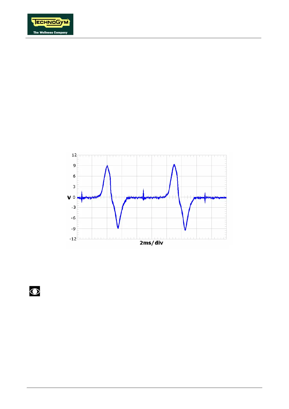
• Pulses
This is the signal produced by the speed sensor, and has the waveform shown in the figure
below:
Figure 3.2-1
The signal enters the Brake Board (pins 3-4 on connector CN2), where it is used to determine
the speed value (RPM)that is sent to the Display Board via the RS-485 serial link.
This signal can also be measured qualitatively using a multimeter. The voltage measured
across the sensor terminals should be 0 Vdc when the machine is stopped, and should increase
to a few hundred mV during pedal movement: the higher the speed, the higher the measured
voltage.