Adjustment Procedure— 2230 Service
h. ADJUST—MF/LF Comp (C3) and MF/LF Gain Bal
(R47) for the best front corner and flat top.
i. Disconnect the test equipment from the instrument.
6. Adjust Vertical Gain (R145, R195, R76, and R26)
a. Connect a 50 mV standard-amplitude signal from
the Calibration Generator via a 50 0 cable to the CH 1 OR
X input connector.
b. Set the A SEC/DIV switch to 0.2 ms.
c. Center the display within the graticule using the
Channel 1 POSITION control.
d. ADJUST—Ch 1 Gain (R145) for an exact 5-division
display.
e. Move the cable from the CH 1 OR X input connector
to the CH 2 OR Y input connector. Set the VERTICAL
MODE switch to CH 2.
f. Center the display within the graticule using the
Channel 2 POSITION control.
g. ADJUST—Ch 2 Gain (R195) for an exact 5-division
display.
h. Change the generator output to 10 mV and set both
VOLTS/DIV switches to 2 mV.
i. Repeat parts d and g until the gain of the two chan
nels is identical.
J. ADJUST—2 mV Gain (R76) for an exact 5-division
display.
k. Move the cable from the CH 2 OR Y input connector
to the CH 1 OR X input connector. Set the VERTICAL
MODE switch to CH 1.
l. ADJUST—2 mV Gain (R26) for an exact 5-division
display.
m. Set both AC-GND-DC switches to GND.
n. CHECK—That no trace shift occurs when switching
between the 5 mV and 2 mV positions of the CH 1
VOLTS/DIV switch. If trace shift is observed, repeat
Step 2 of this procedure.
o. Set the VERTICAL MODE switch to CH 2.
p. CHECK—That no trace shift occurs when switching
between the 5 mV and 2 mV positions of the CH 2
VOLTS/DIV switch. If trace shift is observed, repeat
Step 2 of this procedure.
7. Check Deflection Accuracy and Variable Range
a. Set:
VERTICAL MODE CH 1
AC-GND-DC (both) DC
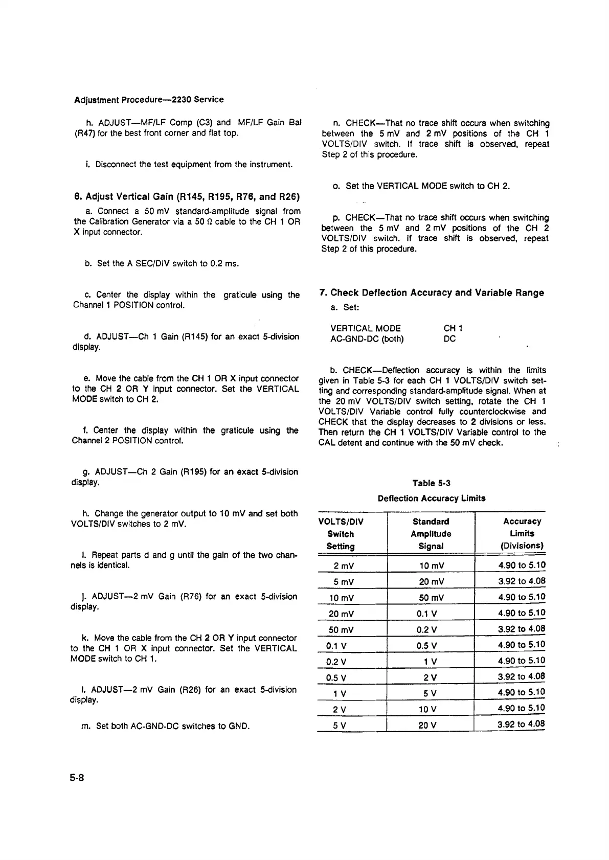
b. CHECK—Deflection accuracy is within the limits
given in Table 5-3 for each CH 1 VOLTS/DIV switch set
ting and corresponding standard-amplitude signal. When at
the 20 mV VOLTS/DIV switch setting, rotate the CH 1
VOLTS/DIV Variable control fully counterclockwise and
CHECK that the display decreases to 2 divisions or less.
Then return the CH 1 VOLTS/DIV Variable control to the
CAL detent and continue with the 50 mV check.
Table 5-3
Deflection Accuracy Limits
VOLTS/DIV
Switch
Setting
Standard
Amplitude
Signal
Accuracy
Limits
(Divisions)
2 mV
10 mV
4.90 to 5.10
5 mV
20 mV
3.92 to 4.08
10 mV
50 mV
4.90 to 5.10
20 mV
0.1 V
4.90 to 5.10
50 mV
0.2 V
3.92 to 4.08
0.1 V
0.5 V
4.90 to 5.10
0.2 V
1 V
4.90 to 5.10
0.5 V
2 V
3.92 to 4.08
1 V
5 V
4.90 to 5.10
2 V
10 V
4.90 to 5.10
5 V
20 V
3.92 to 4.08
5-8