Adjustm ent Procedure— 2230 Service
I. Position the trace 0.5 division below the top horizon
tal graticule line using the Channel 1 POSITION control.
g. ADJUST—Ch 1 Acq Gain (R2118) for an exact 5-
division display.
m. Set SAVE/CONTINUE switch to SAVE (button in).
n. CHECK—Trace shift of 0.5 division or less.
o. Set SAVE/CONTINUE switch to CONTINUE (button
out).
p. Position the trace 0.5 division above the bottom hor
izontal graticule line using the Channel 1 POSITION
control.
q. Set SAVE/CONTINUE switch to CONTINUE (button
out).
r. CHECK— Trace shift of 0.5 division or less.
s. Set the VE R TIC A L M O D E switch to C H 2.
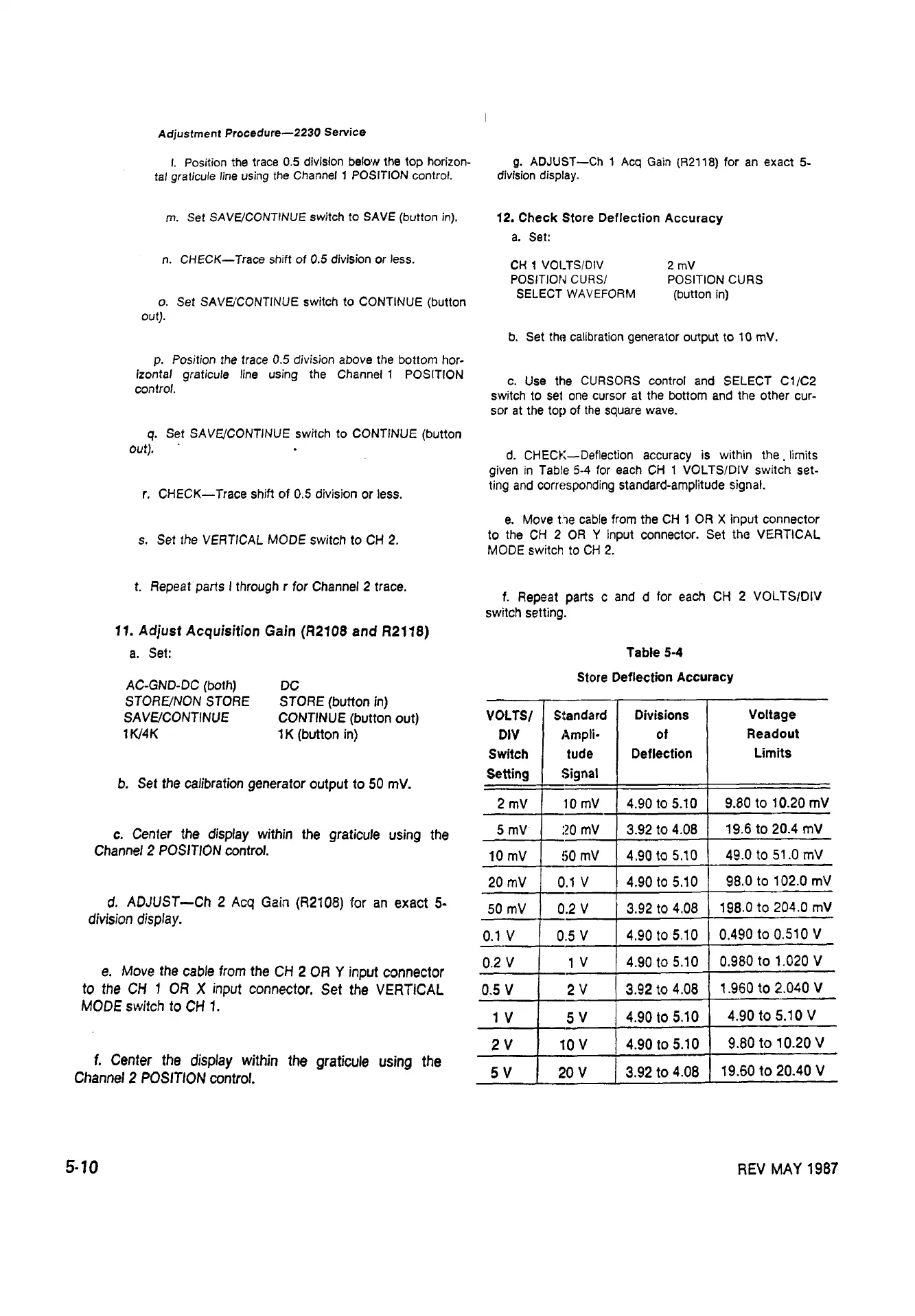
1 2 . Check Store Deflection Accuracy
a. Set:
CH 1 VOl.TS/DIV 2 mV
POSITION CURS/ POSITION CURS
SELECT WAVEFORM (button in)
b. Set the calibration generator output to 10 mV.
c. Use the CURSORS control and SELECT C1/C2
switch to set one cursor at the bottom and the other cur
sor at the top of the square wave.
d. CHECK— Deflection accuracy is within th e . limits
given in Table 5-4 for each CH 1 VOLTS/DIV switch set
ting and corresponding standard-amplitude signal.
e. Move the cable from the CH 1 OR X input connector
to the CH 2 OR Y input connector. Set the VERTICAL
MODE switch to CH 2.
f. R e p eat parts I through r for Channel 2 trace.
11. Adjust Acquisition Gain (R2108 and R2118)
a. Set:
A C -G N D -D C (both)
S T O R E /N O N STORE
S A V E /C O N T IN U E
1K/4K
DC
STORE (button in)
CONTINUE (button out)
1K (button in)
b. Set the calibration generator output to 50 mV.
c. Center the display within the graticule using the
Channel 2 POSITION control.
d. ADJUST—Ch 2 Acq Gain (R2108) for an exact 5-
division display.
e. Move the cable from the CH 2 OR Y input connector
to the CH 1 OR X input connector. Set the VERTICAL
MODE switch to CH 1.
f. Center the display within the graticule using the
Channel 2 POSITION control.
f. Repeat parts c and d for each CH 2 VOLTS/DIV
switch setting.
Table 5-4
Store Deflection Accuracy
VOLTS/
DIV
Switch
Setting
Standard
Ampli
tude
Signal
Divisions
of
Deflection
Voltage
Readout
Limits
2 mV
10 mV 4.90 to 5.10
9.80 to 10.20 mV
5 mV 20 mV
3.92 to 4.08
19.6 to 20.4 mV
10 mV 50 mV
4.90 to 5.10
49.0 to 51.0 mV
20 mV
0.1 V
4.90 to 5.10
98.0 to 102.0 mV
50 mV
0.2 V 3.92 to 4.08
198.0 to 204.0 mV
0.1 V
0.5 V 4.90 to 5.10
0.490 to 0.510 V
0.2 V 1 V
4.90 to 5.10
0.980 to 1.020 V
0.5 V
2 V 3.92 to 4.08
1.960 to 2.040 V
1 V
5 V 4.90 to 5.10
4.90 to 5.10 V
2 V
10 V 4.90 to 5.10
9.80 to 10.20 V
5 V
20 V
3.92 to 4.08
19.60 to 20.40 V
5-10
REV MAY 1987