Adjustment Procedure—2230 Service
h. Set the SAVE/CONTINUE switch to SAVE (button
in).
i. Set the CH 2 VOLTS/DIV switch to 1 V.
j. CHECK—The display is compressed to 0.5 division
in amplitude.
k. Move the cable from the CH 2 OR Y input connector
to the CH 1 OR X input connector.
i. Set:
VERTICAL MODE CH 1
SAVE/CONTINUE CONTINUE (button out)
m. Repeat parts c through j.
n. Disconnect the test equipment from the instrument.
16. Adjust Attenuator Compensation
(C12, C11, C5, C4, C62, C61, C55, C54)
a. Set:
VOLTS/DIV (both) 0.1 V
STORE/NON STORE NON STORE (button out)
b. Connect the high-amplitude square wave output via
a 50 0 termination, a probe-tip-to-BNC adapter, and the
10X probe to the CH 1 OR X input connector.
c. Set the generator to produce a 1 kHz, 5-division
display and compensate the probe using the probe com
pensation adjustment (see the probe instruction manual).
d. Set the CH 1 VOLTS/DIV switch to 0.1 V.
e. Replace the probe and probe-tip-to-BNC adapter
with a 50 Q cable.
f. Set the generator to produce a 5-division display.
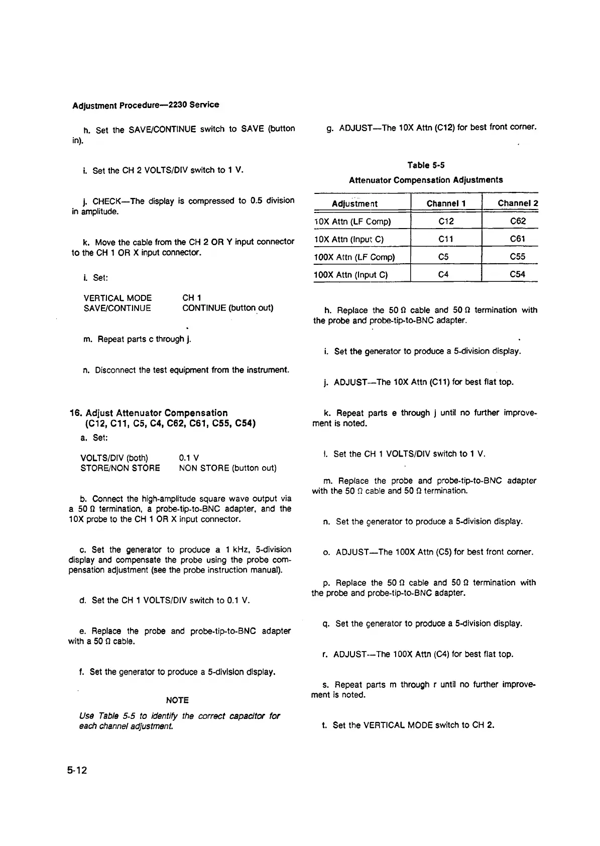
NOTE
Use Table 5-5 to identify the correct capacitor for
each channel adjustment.
g. ADJUST—The 10X Attn (Cl 2) for best front corner.
Table 5-5
Attenuator Compensation Adjustments
Adjustment
Channel 1
Channel 2
10X Attn (LF Comp)
Cl 2 C62
10X Attn (Input C)
C11
C61
100X Attn (LF Comp) C5
C55
100X Attn (Input C)
C4 C54
h. Replace the 50 Si cable and 50 Si termination with
the probe and probe-tip-to-BNC adapter.
i. Set the generator to produce a 5-division display.
j. ADJUST—The 10X Attn (C11) for best flat top.
k. Repeat parts e through j until no further improve
ment is noted.
l. Set the CH 1 VOLTS/DIV switch to 1 V.
m. Replace the probe and probe-tip-to-BNC adapter
with the 50 S2 cable and 50 Si termination.
n. Set the generator to produce a 5-division display.
o. ADJUST—The 100X Attn (C5) for best front corner.
p. Replace the 50 S2 cable and 50 SI termination with
the probe and probe-tip-to-BNC adapter.
q. Set the generator to produce a 5-division display.
r. ADJUST—The 100X Attn (C4) for best flat top.
s. Repeat parts m through r until no further improve
ment is noted.
t. Set the VERTICAL MODE switch to CH 2.
5-12