The Holdoff setting range is 0 s (minimum holdoff available) to 10 s (maximum holdoff available). For more information on how to
set holdoff, see Set Trigger Holdoff on page 119. If you select Auto holdoff, the instrument selects a holdoff value for you. When
Trigger Holdoff is set to Random, the instrument delays the trigger a random amount of time between triggers. This means that
successive acquisitions are unrelated to the previous trigger signal.
Trigger coupling
Trigger coupling determines what part of the signal is passed to the trigger circuit. Edge triggering can use all available coupling
types: DC, Low Frequency Rejection, High Frequency Rejection, and Noise Rejection. All of the advanced trigger types use DC
coupling only.
■
DC. This coupling passes all input signals to the trigger circuitry.
■
HF Reject. This coupling attenuates signals above 50 kHz before passing the signal to the trigger circuitry.
■
LF Rej. This coupling attenuates signals below 50 kHz before passing the signal to the trigger circuitry.
■
Noise Rej. This coupling provides stable triggering by increasing the trigger hysteresis. Increased hysteresis reduces the
trigger sensitivity to noise but may require greater signal amplitude.
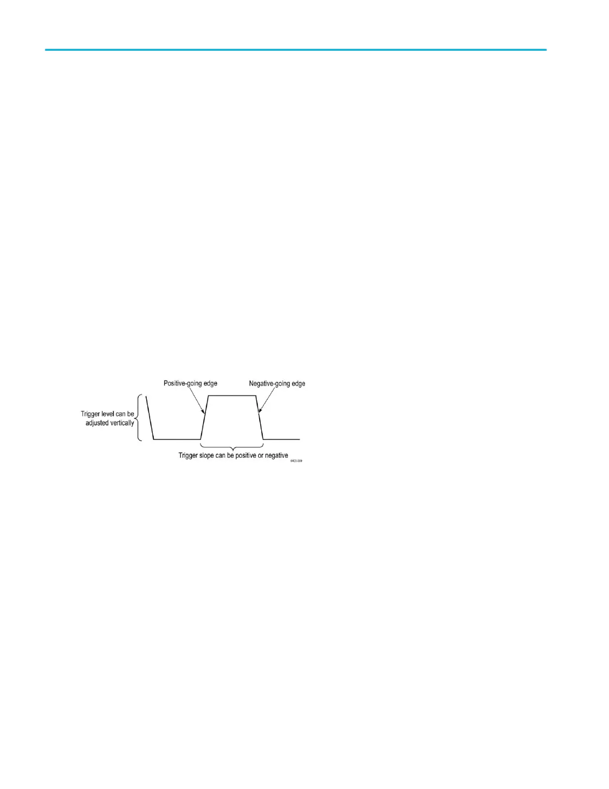
Trigger slope and level
The slope control determines whether the instrument finds the trigger point on the rising or the falling edge of a signal. The level
control determines where on that edge the trigger point occurs. See the next figure.
Trigger position in waveform record
Trigger position is an adjustable feature that defines where the trigger occurs on the waveform record. It lets you choose how
much the instrument acquires before and after the trigger event. The part of the record that occurs before the trigger is the
pretrigger portion. The part that occurs after the trigger is the posttrigger portion. A longer posttrigger period may be useful when
you want to see the effects an event has on your system under test.
Pretrigger data can be valuable when troubleshooting. For example, if you are trying to find the cause of an unwanted glitch in
your test circuit, you can trigger on the glitch and make the pretrigger period large enough to capture data before the glitch. By
analyzing what happens before the glitch, you may uncover information that helps you find the source of the glitch.
Trigger concepts
422 MSO54, MSO56, MSO58, MSO58LP, MSO64 Help