239
At the longer holdoff time for the top waveform, unstable triggering occurs. With a shorter holdoff
set for the bottom waveform, triggers all occur on the first pulse in the burst to remedy the
unstable trigger.
The Holdoff setting range is 1.5 µs (minimum holdoff available) to 12 seconds (maximum holdoff
available). For more information on how to set holdoff, see page 122. You can also set a default
holdoff. The default holdoff is the general-purpose holdoff for most applications and varies with
the horizontal scale. It is equal to five times the current horizontal scale setting.
Trigger Coupling
Trigger coupling determines what part of the signal is passed to the trigger circuit. Edge triggering
can use all available coupling types: AC, DC, Low Frequency Rejection, High Frequency
Rejection, and Noise Rejection. All of the advanced trigger types use DC coupling only. For a
description of each coupling type, see the Glossary.
Horizontal Trigger Position
Horizontal position is an adjustable feature that defines where the trigger occurs on the waveform
record. It lets you choose how much the instrument acquires before and after the trigger event. The
part of the record that occurs before the trigger is the pretrigger portion. The part that occurs after
the trigger is the posttrigger portion. A longer posttrigger period my be useful when you want ot
see the effects an event has on your system under test.
Pretrigger data can be valuable when troubleshooting. For example, if you are trying to find the
cause of an unwanted glitch in your test circuit, you can trigger on the glitch and make the
pretrigger period large enough to capture data before the glitch. By analyzing what happens before
the glitch, you may uncover information that helps you find the source of the glitch.
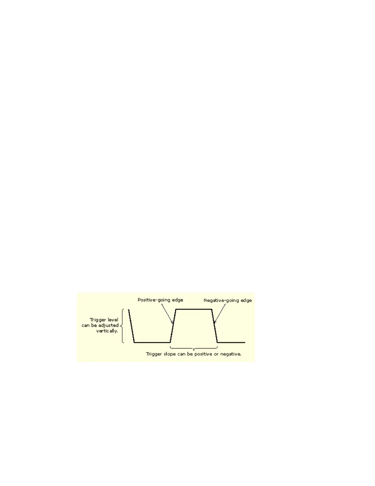
Trigger Slope and Level
The slope control determines whether the instrument finds the trigger point on the rising or the
falling edge of a signal. The level control determines where on that edge the trigger point occurs.
See the figure below.
Delayed Trigger System
You can trigger with the A (Main) trigger system alone or you can combine the A (Main) trigger
with the B (Delayed) trigger to trigger on sequential events. When using sequential triggering, the
A trigger event arms the trigger system, and the B trigger event triggers the instrument when the B
trigger conditions are met. A and B triggers can (and typically do) have separate sources. The B
trigger condition can be based on a time delay or a specified number of counted events. For more
details on delayed triggering see page 120.
 Loading...


