85
Note
The 50 Ω termination becomes an open circuit if you set the channel input coupling to GND.
Consider the following when using 50 Ω termination with any channel:
The instrument does not accurately display frequencies under 200 kHz with AC coupling.
The instrument reduces the maximum vertical scale setting for the channel to 1 V from 10 V
(to 10 V from 100 V with a 10 X probe attached), since the amplitudes appropriate for the
higher settings would overload the 50 Ω input.
The instrument switches to 50 Ω and disables AC coupling (and switches coupling to DC if
AC is selected) if you connect an active probe. The active probes also reduce the maximum
vertical scale setting as described above. This behavior results in 50 Ω, nonAC coupling,
which is appropriate for active probes.
Note
If you remove an active probe, the instrument does not switch coupling back to 1 MΩ or AC.
When you restore 1 MΩ coupling, the instrument does not return to the vertical scale setting that
was reduced because of the 50 Ω selection. You must set the vertical scale, coupling, and
termination appropriate for your input coupling scheme. Be sure to switch to 1 MΩ for any input
signal not from a 50 Ω system.
Use the button on the front panel of each vertical input channel to manually select the
termination.
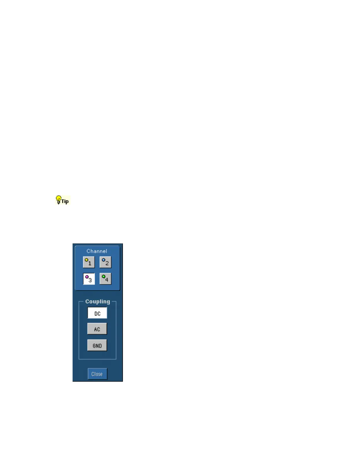
Coupling Control Window
Access this control window from the Vertical menu Coupling command.
Overview
Use the Coupling control window to select the coupling for the signal
from the attached probe to the instrument.
To Use
Click a Channel button at the top of the control window to select the
vertical input channel. Click one of the Coupling controls to couple
the signal from the probe to the instrument.
Behavior
Select DC coupling to display the waveform with the DC and AC
components.
Select AC coupling to display the waveform with the DC component
removed.
Select GND to display a zero-volt waveform. Use this selection to
establish the ground reference point on the display
 Loading...


