60
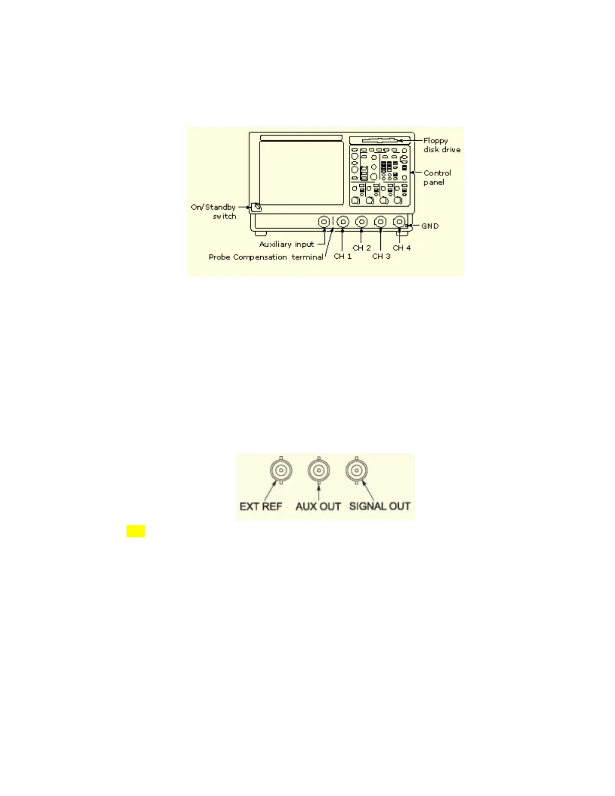
Front Panel Connectors
The instrument features these front panel connectors:
The trigger level range for the auxiliary input (AUX IN) is adjustable from +8 V to –8 V. The
maximum input voltage is ±20 V.
Use the probe compensation terminals (PROBE COMP) to compensate, calibrate, and deskew
passive or active voltage probes.
Connect up to four probes (two probes for 2-channel models) to input channels (CH n) of the
instrument. Each vertical input channel has its own vertical control settings. Each probe input
channel has its own TekProbe interface.
Use the ground (GND) terminal to connect the instrument to the same ground as the unit
under test.
Rear Panel Connectors
The instrument features these rear panel connectors:
Use the EXT REF connector to synchronize the instrument time base to an external 9.8 −
10.2 MHz reference frequency source. The reference input voltage range is 200 mV
p-p to 7Vp-p.
Use the AUX OUT connector to obtain a TTL-compatible, negative polarity pulse when the
instrument triggers.
Use the SIGNAL OUT connector to connect to a buffered version of the signal that is
attached to the Channel 3 input (4-channel instruments only). The amplitude is 50 mV/div
±20% into a 1 MΩ load, or 25 mV/div ±20% into a 50 Ω load.
 Loading...


