Appendix E
Installation manual to TCS5500 Appendix E ● 111
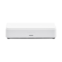
On this set, there is:
a slide switch ON/OFF: when testing, you turn the switch to
ON.
a SUBD 9 connector (an adapter to the RJ-45 connecter is
supplied with the tester).
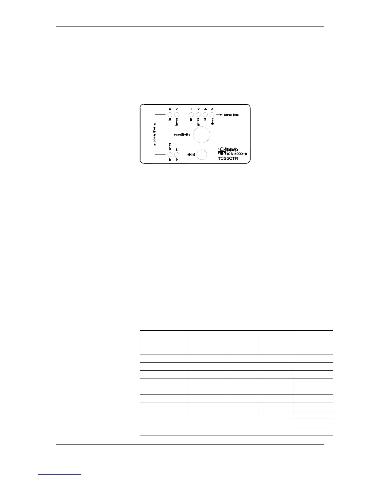
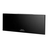
Televic cable tester receiver CTR5500
Fig.: CTR5500
On this set, there are:
4 leds for the ‘signal lines’ + corresponding pin number and
color wire
4 leds for the ‘power lines’ + corresponding pin number and
color wire
a turn switch: sensitivity tuning
a push button: start test
a SUBD 9 connector
Note that the TMS5500 and TIS5500 network uses RJ45
connectors in stead of the SUBD 9 connectors which were used in
previous versions of the Televic conference system. Therefore a
connector converter is necessary to test the cabling in the network.
The numbers on the CTR correspond to the pin numbers on the
SUBD 9 connector. The table below describes the translation
between the SUBD 9 and RJ45 connector.