www.ti.com
Input Capture Mode
10.4 Input Capture Mode
When a channel is configured as an input capture channel, the I/O pin associated with that channel is
configured as an input. After the timer has been started, a rising edge, falling edge, or any edge on the
input pin triggers a capture of the 8-bit counter contents into the associated capture register. Thus, the
timer is able to capture the time when an external event takes place.
NOTE: Before an I/O pin can be used by the timer, the required I/O pin must be configured as a
Timer 3/Timer 4 peripheral pin.
The channel input pin is synchronized to the internal system clock. Thus, pulses on the input pin must
have a minimum duration greater than the system clock period.
The content of the 8-bit capture register for channel n is read out from register T3CCn/T4CCn.
When the capture takes place, the interrupt flag for the channel, TIMIF.TxCHnIF (x is 3 or 4, n is the
channel number), is set. An interrupt request is generated if enabled, see Section 10.6 for details.
10.5 Output Compare Mode
In output-compare mode, the I/O pin associated with a channel must be set to an output. After the timer
has been started, the content of the counter is compared with the contents of channel compare register
TxCC0n. If the compare register equals the counter contents, the output pin is set, reset, or toggled
according to the compare output mode setting of TxCCTL.CMP1:0. Note that all edges on output pins are
glitch-free when operating in a given compare output mode.
For simple PWM use, output compare modes 4 and 5 are preferred.
Writing to compare register TxCC0 or TxCC1 does not take effect on the output compare value until the
counter value is 0x00.
When the capture takes place, the interrupt flag for the channel, TIMIF.TxCHnIF (x is 3 or 4, n is the
channel number), is set. An interrupt request is generated if enabled, see Section 10.6 for details.
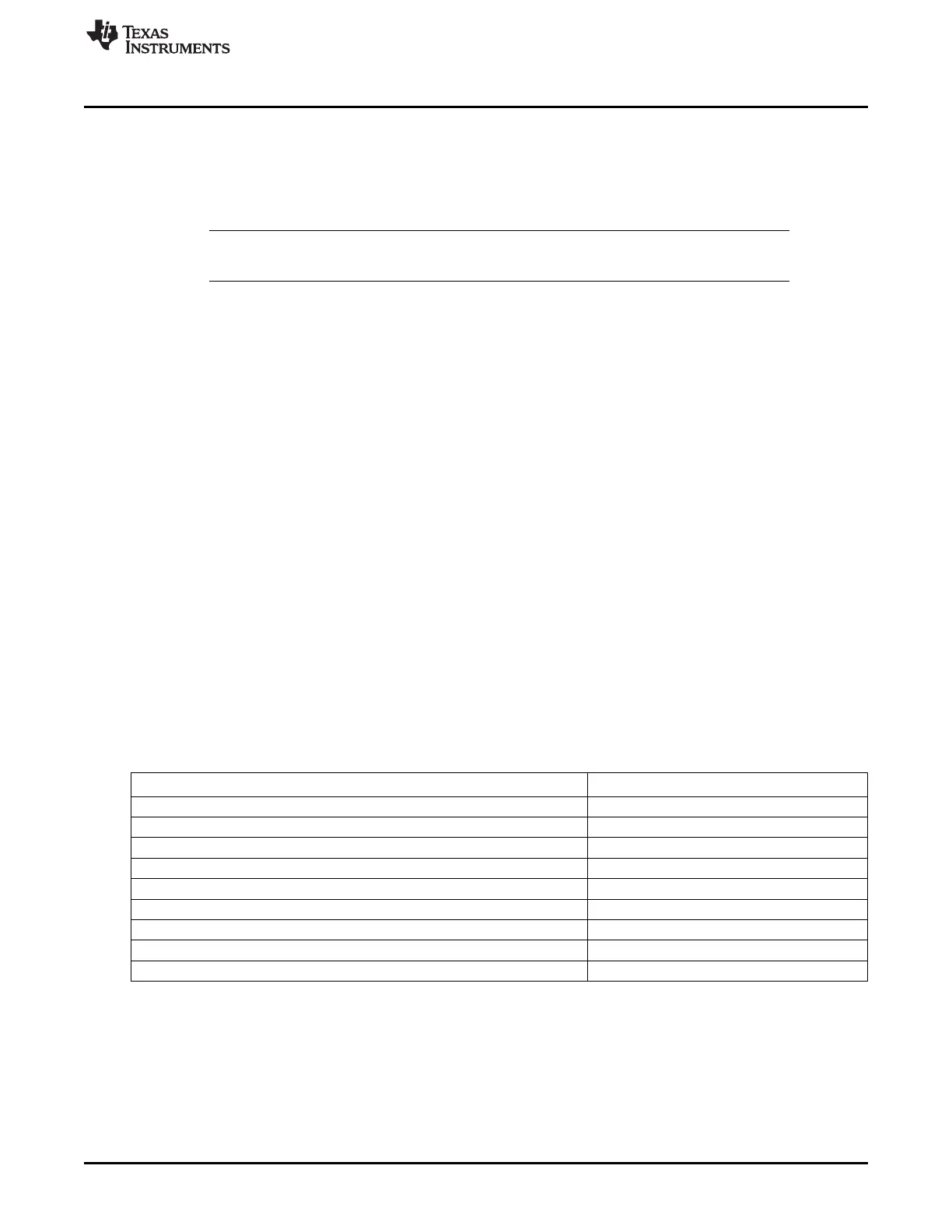
A compare output pin is initialized to the value listed in Table 9-1 when:
• a 1 is written to TxCNTR.CLR (All Timer x channels)
• 0x7 is written to TxCCTLn.CMP (Timer x, channel n)
Table 10-1. Initial Compare Output Values (Compare Mode)
Initial Compare Output
Compare Mode (TxCCTLn.CMP)
Set output on compare (000) 0
Clear output on compare (001) 1
Toggle output on compare (010) 0
Set output on compare-up, clear on compare-down in up-down mode (011) 0
In other modes than up-down mode, set output on compare, clear on 0 (011) 0
Clear output on compare-up, set on compare-down in up-down mode (100) 1
In other modes than up-down mode, clear output on compare, set on 0 (100) 1
Set output on compare, clear on 0xFF (101) 0
Clear output on compare, set on 0x00 (110) 1
10.6 Timer 3 and Timer 4 Interrupts
One interrupt vector is assigned to each of the timers. These are T3 and T4. An interrupt request is
generated when one of the following timer events occurs:
• Counter reaches terminal count value.
• Compare event
• Capture event
127
SWRU191C–April 2009–Revised January 2012 Timer 3 and Timer 4 (8-Bit Timers)
Submit Documentation Feedback
Copyright © 2009–2012, Texas Instruments Incorporated
 Loading...


