www.ti.com
Memory
contain page-lock bits and the debug-lock bit. There is one lock bit for each page, except the lock-bit page
which is implicitly locked when not in debug mode. When the lock bit for a page is 0, it is impossible to
erase/write that page. When the debug lock bit is 0, most of the commands on the debug interface are
ignored. The primary purpose of the debug lock bit is to protect the contents of the flash against read-out.
The Flash Controller is used to write and erase the contents of the flash memory.
When the CPU reads instructions and constants from flash memory, it fetches the instructions through a
cache. Four bytes of instructions and four bytes of constant data are cached, at 4-byte boundaries. That
is, when the CPU reads from address 0x00F1 for example, bytes 0x00F0–0x00F3 are cached. A separate
prefetch unit is capable of prefetching 4 additional bytes of instructions. The cache is provided mainly to
reduce power consumption by reducing the amount of time the flash memory is accessed. The cache may
be disabled with the FCTL.CM[1:0] register bits. Doing so increases power consuption and is not
recommended. The execution time from flash is not cycle-accurate when using the default cache mode
and the cache mode with prefetch, i.e., one cannot determine exactly the number of clock cycles a set of
instructions takes. To obtain cycle-accurate execution, enable the real-time cache mode and ensure all
DMA transfers have low priority. The prefetch mode improves performance by up to 33%, at the expense
of increased power consumption due to wasted flash reads. Typically, performance improves by
15%–20%. Total energy, however, may decrease (depending on the application) due to fewer wasted
clock cycles waiting for the flash to return instructions/data. This is very application-dependent and
requires the use of power modes to be effective.
The Information Page is a 2-KB read-only region that stores various device information. Among other
things, it contains for IEEE 802.15.4 or Bluetooth low energy compliant devices a unique IEEE address
from the TI range of addresses. For CC253x, this is a 64-bit IEEE address stored with least-significant
byte first at XDATA address 0x780C. For CC2540/41, this is a 48-bit IEEE address stored with
least-significant byte first at XDATA address 0x780E.
SFR Registers. The special function registers (SFRs) control several of the features of the 8051 CPU
core and/or peripherals. Many of the 8051 core SFRs are identical to the standard 8051 SFRs. However,
there are additional SFRs that control features that are not available in the standard 8051. The additional
SFRs are used to interface with the peripheral units and RF transceiver.
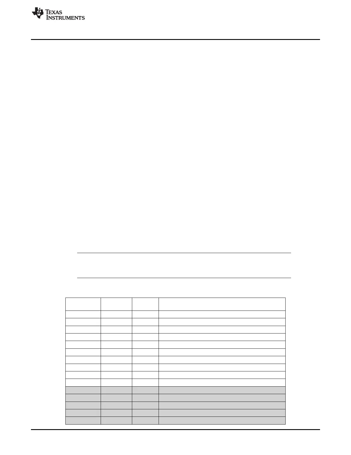
Table 2-1 shows the addresses of all SFRs in the device. The 8051 internal SFRs are shown with gray
background, whereas the other SFRs are the SFRs specific to the device.
NOTE: All internal SFRs (shown with gray background in Table 2-1), can only be accessed through
SFR space, as these registers are not mapped into XDATA space. One exception is the port
registers (P0, P1, and P2) which are readable from XDATA.
Table 2-1. SFR Overview
Register SFR
Module Description
Name Address
ADCCON1 0xB4 ADC ADC control 1
ADCCON2 0xB5 ADC ADC control 2
ADCCON3 0xB6 ADC ADC control 3
ADCL 0xBA ADC ADC data low
ADCH 0xBB ADC ADC data high
RNDL 0xBC ADC Random number generator data low
RNDH 0xBD ADC Random number generator data high
ENCDI 0xB1 AES Encryption/decryption input data
ENCDO 0xB2 AES Encryption/decryption output data
ENCCS 0xB3 AES Encryption/decryption control and status
P0 0x80 CPU Port 0. Readable from XDATA (0x7080)
SP 0x81 CPU Stack pointer
DPL0 0x82 CPU Data pointer 0 low byte
DPH0 0x83 CPU Data pointer 0 high byte
DPL1 0x84 CPU Data pointer 1 low byte
31
SWRU191C–April 2009–Revised January 2012 8051 CPU
Submit Documentation Feedback
Copyright © 2009–2012, Texas Instruments Incorporated
 Loading...


