ELECTRICAL SYSTEM
10C-8
WIRE CONTINUITY TEST
1. Identify and locate the wire to be checked on the
appropriate wiring diagram (Section 10Q).
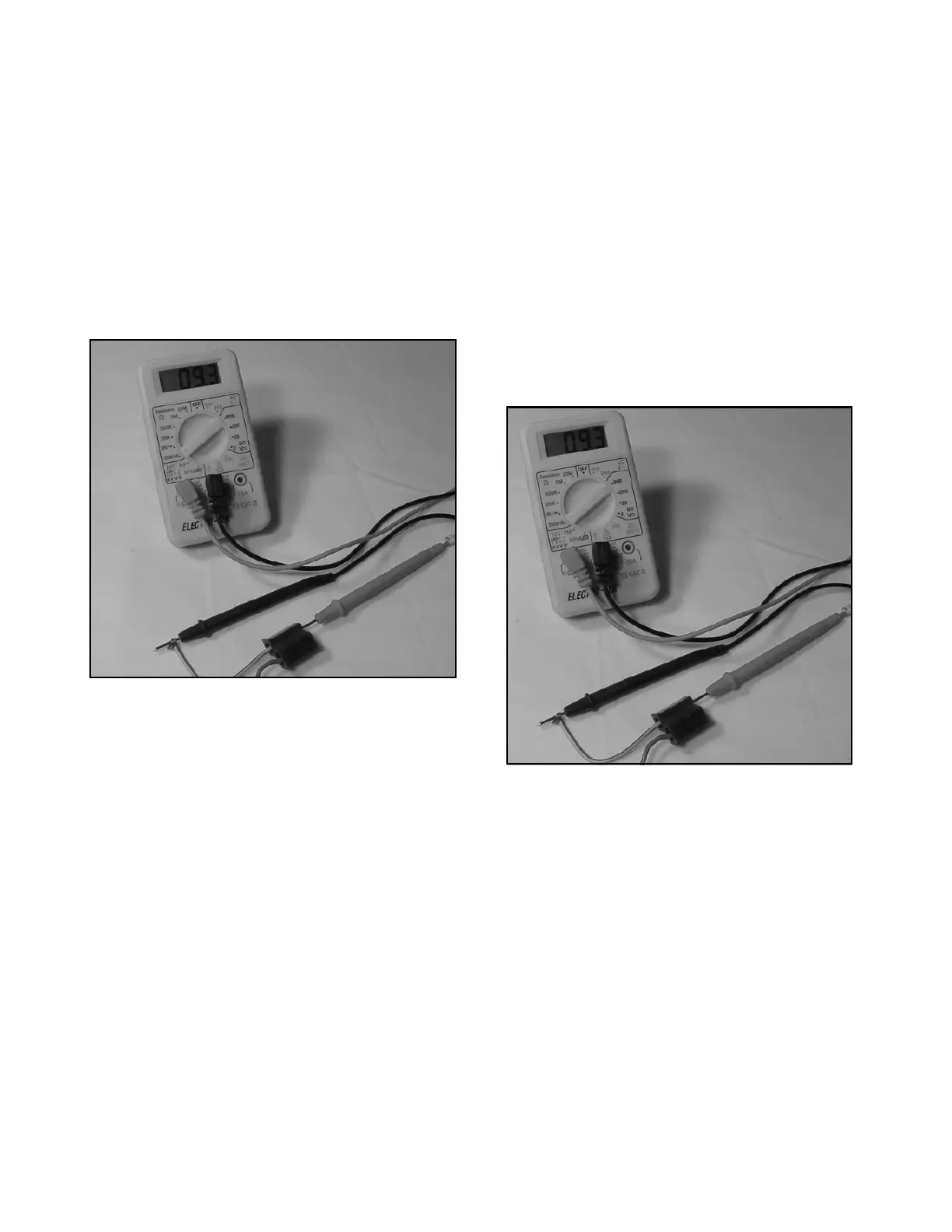
2. Set the multimeter to ohm —|← scale and touch
the leads to the end of the wire.
There should be a reading (continuity) on the mul-
timeter and buzzer (Figure 10C-1).
3. Perform a second check by using a jumper wire to
bypass the wiring being tested. If the component
in question now functions normally, replace the
original wire (Figure 10C-2).
Figure 10C-2. Continuity Test
RESISTANCE TEST
Resistance is measured in Ohms (Ω). Using a multim-
eter the resistance in a circuit can be tested
(Figure 10C-3).
1. Set the multimeter to the
Ω scale.
2. Connect the positive (+POS) lead to one terminal
on the wire or switch.
3. Read the
Ω (OHMS) on the multimeter.
Contacts of a switch or a wire should have less
that 0.5
Ω (OHMS) reading.
If
Ω (OHMS) readings are above 0.5 the switch or
wire is questionable.
Figure 10C-3. Resistance Tests
 Loading...


