STEERING
6C-10
27.Install the o-rings (4) and seal ring (3) on the port
cover (2).
28.Install the needle rollers (5) in the port manifold
(6).
29.Install the port manifold (6).
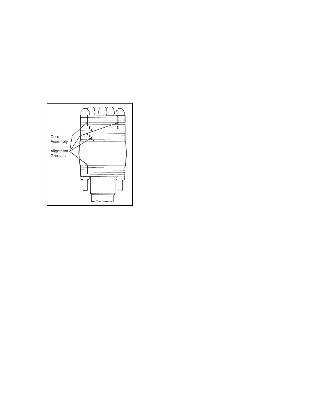
30.Install the lock nuts (1). Tighten the lock nuts grad-
ually in sequence to 20-24 ft-lbs (27-33 Nm)
torque, see Figure 6C-7.
31.Install the relief valve assembly (5) into the port
cover (2).
Figure 6C-7. Alignment Grooves
INSTALLATION
1. Place the steering valve in the steering unit
bracket with the four studs protruding through the
bracket.
2. Install the steering unit mounting nuts.
3. Install the steering wheel, lockwasher, and nut.
Tighten the nut to 25-30 ft-lbs (34-41 Nm) torque.
4. Remove the plugs from the steering valve and
hydraulic hoses. Using the tags created during
disassembly, connect the hoses to the steering
valve.
5. Install the steering tower cover.
 Loading...


