ELECTRICAL SYSTEM
10E-11
SECTION 10E. CHARGING SYSTEM
GENERAL
The charging system consists of a 40-amp alternator
with a built in rectifier/regulator.
The alternator must be disassembled to test the stator,
rotor, and rectifier. Refer to the engine manufacturer’s
service manual for detailed test and repair instructions.
Before attempting to disassemble the alternator, per-
form the following tests to confirm the alternator is at
fault.
OUTPUT VOLTAGE TEST
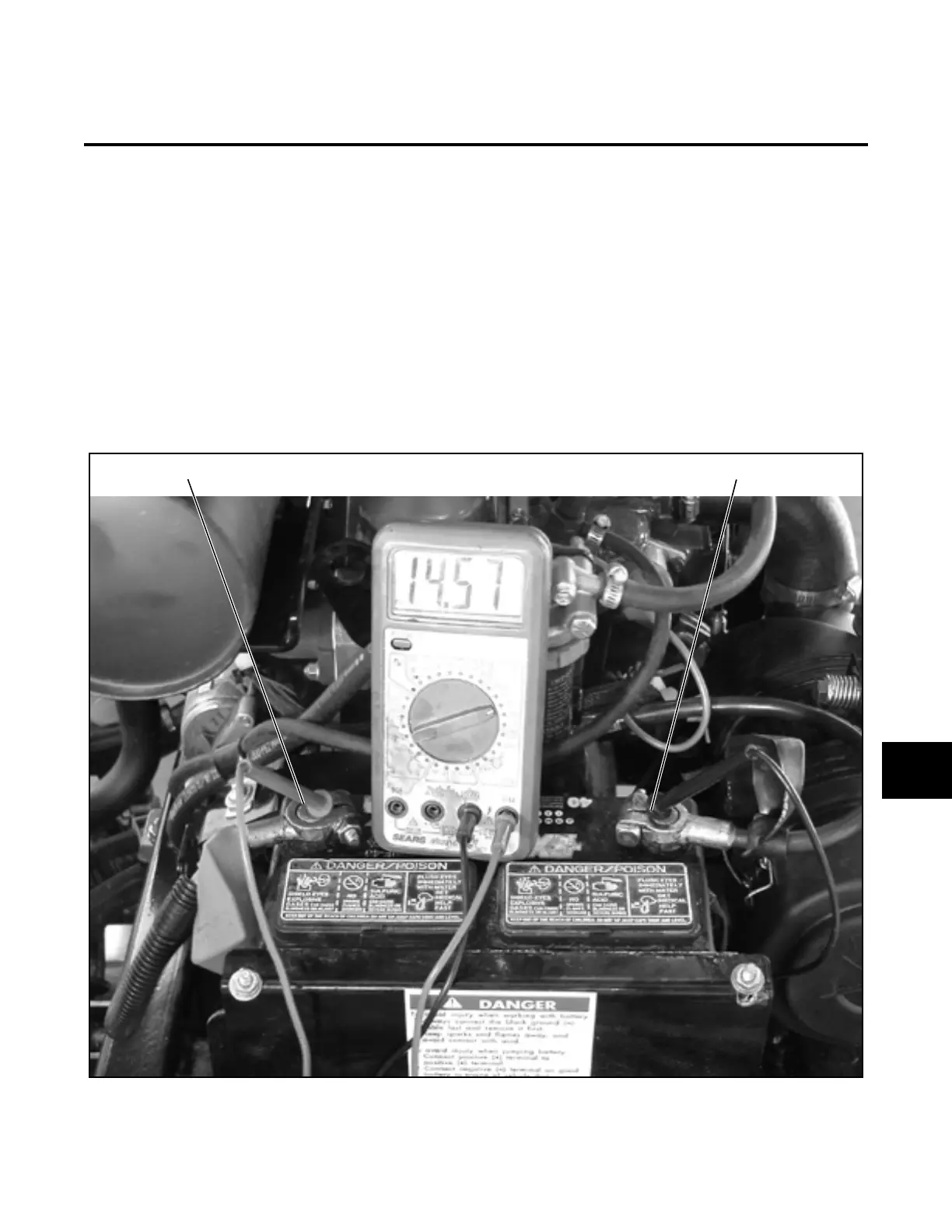
1. Set the multimeter to 20 DC volts.
2. Place the red (+ POS) lead on the positive termi-
nal, and the black (- NEG) lead on the negative
terminal (Figure 10E-1).
3. Using the precautions outlined in the operator’s
manual, start the engine.
As the engine rpm increases, voltage should
increase to 13.5 volts.
If NO voltage is measured, proceed with Step 7.
If voltage does not start coming down after a short
running period, battery may be faulty or regulator/
rectifier may be faulty.
Figure 10E-1. Output Voltage Test
(+) POS (-) NEG
10E
 Loading...


