ELECTRICAL SYSTEM
10G-21
NOTE:
Replace the switch if it does not meet the above
test results.
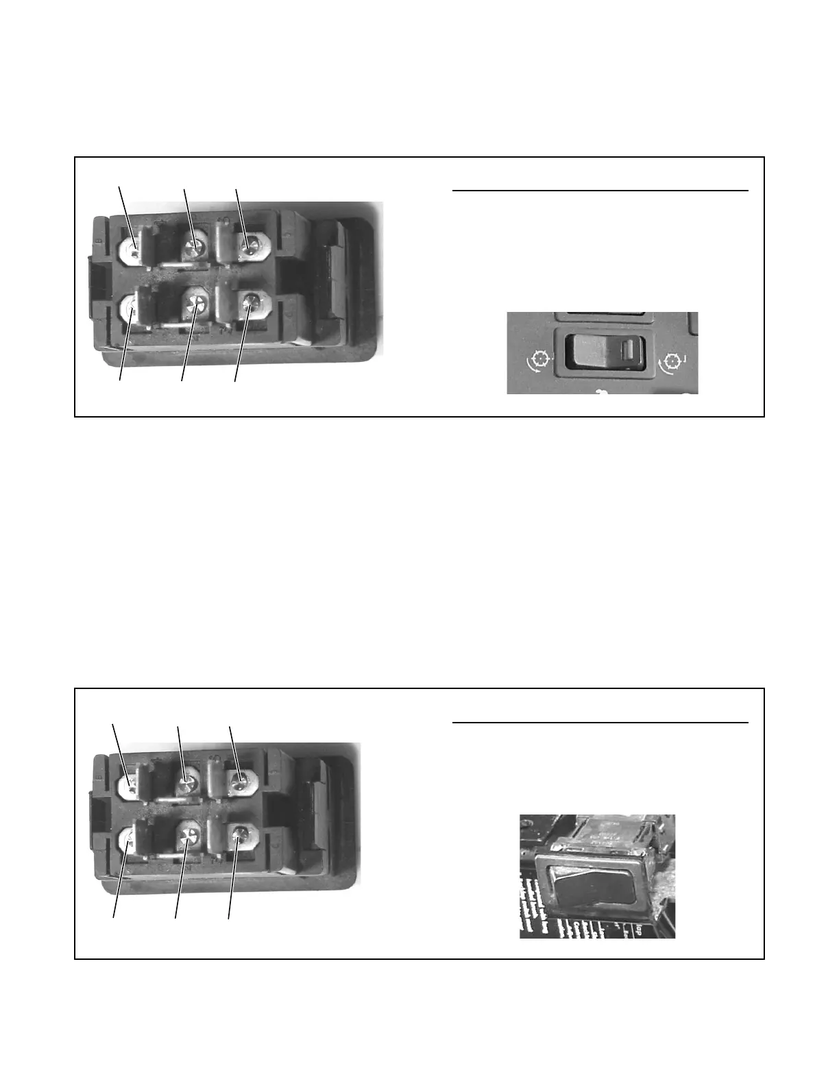
Figure 10G-5. Reel Switch
BACKLAP SWITCH TEST
The backlap switch is mounted to the rear of the fuse/
relay boxes. The switch has two positions (ON/OFF)
used in conjunction with the reel switch to control the
reverse rotation of the hydraulic reel motors. The
switch can be tested as follows:
1. Shut down the engine and remove the ignition
key.
2. Locate the backlap switch and remove the wiring
harness connector, see Figure 10G-6.
3. Set the multimeter to the continuity scale.
4. Place the switch in the OFF position
(Figure 10G-6). Check continuity between all ter-
minals.
Continuity should be available between terminal 2
and terminal 1 and between terminal 5 and termi-
nal 4 only.
5. Place switch in the ON position. Check continuity
between all terminals (Figure 10G-6).
Continuity should be available between terminal 2
and terminal 3 and between terminal 5 and termi-
nal 6 only.
NOTE:
Replace the switch if it does not meet the above
test results.
Figure 10G-6. Backup Switch
Position Terminal Continuity
OFF None
FWD ON 1& 2 and 4 & 5
REV ON 2 & 3 and 5 & 6
If other terminals test with continuity, the switch
should be replaced.
1
2
654
3
REV
FWD
OFF
Position Terminal Continuity
OFF 1& 2 and 4 & 5
ON 2 & 3 and 5 & 6
If other terminals test with continuity, the switch
should be replaced.
2
54
3
ON
OFF
6
1