STEERING
6C-7
NOTE:
The metering package should be disassembled
for inspection purposes only. Proceed with
STEP 9 for disassembly and inspection proce-
dures.
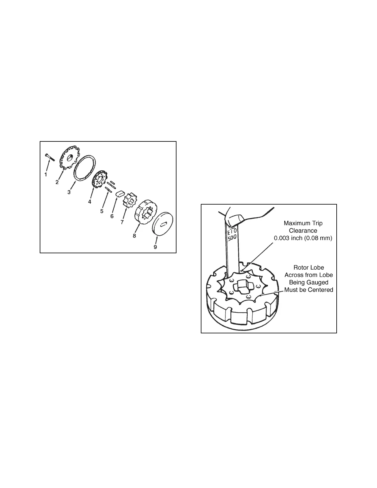
9. Remove the socket head capscrews (1), commu-
tator cover (2), commutator ring (3), and commu-
tator (4), see Figure 6C-3.
10.Remove the five alignment pins (5), see
Figure 6C-3.
11.Remove the drive link spacer (6), rotor (7), and
stator (8) from the drive plate (9), see Figure 6C-3.
Figure 6C-3. Metering Package Disassembly
12.Remove the face seal (20), backup ring (21), and
seal spacer (22), see Figure 6C-2.
13.Remove the thrust bearing (19) and spacer (18),
see Figure 6C-2.
14.Remove the upper cover plate (23) and retaining
ring (24), see Figure 6C-2.
15.Remove the special bolts (25), see Figure 6C-2.
16.Remove the steering shaft (26) out of tube (27),
see Figure 6C-2.
17.Remove the bushing (28) and seal (29), see
Figure 6C-2.
18. Remove the relief valve assembly (5) from the
port cover (2).
STEERING VALVE INSPECTION
1. Inspect the springs (7 and 10) for bent, broken, or
distorted coils.
NOTE:
Always replace springs as a set.
2. Inspect the finished ground surfaces of all the
components.
3. Inspect the slot edges and surface for nicks, scor-
ing, and rounding.
NOTE:
The valve ring (8) and valve plate (9) are a
matched set and are not serviceable.
4. Inspect the hex drive (11) for wear.
5. Inspect the isolation manifold (13) for nicks,
scratches, and scoring. A polished wear pattern
due to valve plate rotation is normal.
6. Inspect the drive link (14) for wear and damage.
7. Inspect the thrust bearing (19) for brinelling, spal-
ling, and missing rollers.
8. Discard all seals and seal rings.
9. Inspect the commutator cover (2) and drive plate
(9) for wear and damage. A polished wear pattern
is normal.
10.Inspect the rotor (7) and stator (8) fit, see
Figure 6C-4.
11.Clean and inspect the relief valve assembly (5).
Figure 6C-4. Rotor and Stator Inspection
STEERING VALVE ASSEMBLY
1. Install a new seal (27) and bushing (26) in the
tube (25). Crimp the tube and end in two places,
90° apart.
2. Place the tube (25) and special bolts (28) in the
service fixture.
3. Install a new retaining ring (23) on the shaft (24)
and attach to tube (27).
NOTE:
In the following assembly steps, it is important to
align the components for proper operation of the
 Loading...


