ELECTRICAL SYSTEM
10H-27
SECTION 10H. SENDERS
GENERAL
Senders are used to activate a light or gauge to warn
the operator of a condition in the engine. A temperature
sender monitors engine coolant temperature and dis-
plays the result on a temperature gauge. An oil sender/
switch monitors the engine oil pressure and illuminates
a warning light to warn the operator when the oil pres-
sure drops to a critical level.
COOLANT TEMPERATURE SENDER
TEST
The temperature sender is a rheostat. As temperature
rises, resistance in the sender decreases creating a
ground drawing the temperature gauge indicator to the
hot side.
1. Shut down the engine and remove the ignition
key. Allow the engine to cool completely.
2. Remove the wiring harness connector from the
end of the sender.
3. Set the multimeter to the continuity scale.
4. Place one test lead on the sender wiring harness
connector stud. Place the other test lead on the
base of the sender, see Figure 10H-1.
When cold, continuity should not be available
between the connector stud and base.
If continuity exists during testing or the temperature
switch causes the horn to sound and continuity does
not exist, the temperature sender may be faulty and
should be replaced.
Figure 10H-1. Coolant Temperature Sender
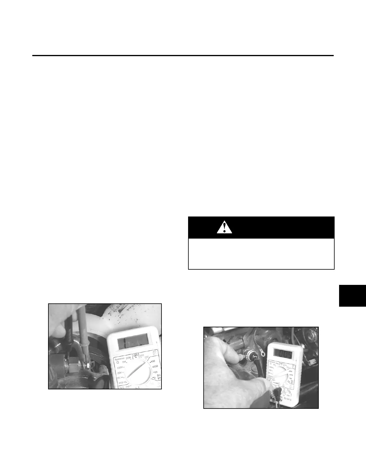
ENGINE OIL PRESSURE SENDER
TEST
The oil pressure sender is pressure sensitive and acts
as a ground for the oil pressure light on the control
panel. When the engine is not running a lack of oil
pressure illuminates the oil light. When the engine
starts and builds pressure the sender opens and the
light goes out.
1. Shut down the engine and remove the ignition
key. Allow the engine to cool completely.
2. Remove the wiring harness connector from the
end of the oil pressure sender.
3. Set the multimeter to the continuity scale.
4. Place one test lead in the end of the sender and
the other test lead on the base of the sender
(Figure 10H-2).
With engine off, continuity should be available
between the end of the sender and the base.
5. Start the engine and perform the continuity test
again.
Continuity should be available between the
sender end and the base with the engine running.
If continuity is not available during testing, the oil pres-
sure sender may be faulty and should be replaced.
Figure 10H-2. Oil Pressure Sender
WARNING
Beware of moving engine parts and do not become
entangled by loose clothing, jewelry, or hair. Serious
injury can occur if caught by moving engine compo-
nents.
10H
 Loading...


