STEERING
6C-6
STEERING VALVE DISASSEMBLY
NOTE:
Before attempting repairs or disassembly of any
hydraulic components, thoroughly clean the com-
ponents and work area. A clean work area is
essential to satisfactory operation of repaired
hydraulic components.
NOTE:
Scribe a line from the top to the bottom of the
steering valve assembly not including the steering
tube. A scribed line can be used for reference dur-
ing assembly for proper assembly of valve sec-
tions.
1. Place the power steering service fixture
(Figure 6A-1) securely in a vise.
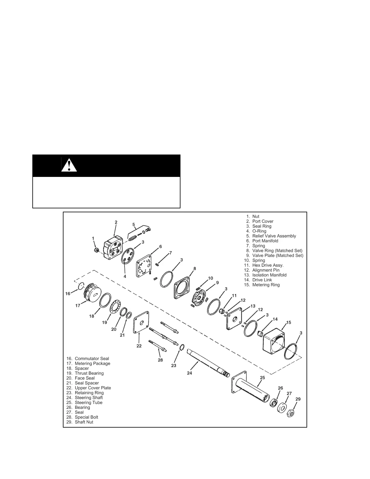
2. Remove the nuts (1) and cover (2), see
Figure 6C-2.
3. Remove the nine needle rollers (5), see
Figure 6C-2.
4. Carefully remove the port manifold (6). Be pre-
pared to catch the three springs (7). Remove the
springs (Figure 6C-2.).
5. Remove the valve ring (8), valve plate springs
(10), and valve plate (9), see Figure 6C-2.
6. Remove the hex drive (11) and isolation manifold
(13), see Figure 6C-2.
NOTE:
Secure the alignments pins (12) to prevent loss,
see Figure 6C-2.
7. Remove the drive link (14) and metering ring (15),
see Figure 6C-2.
8. Remove the metering package (17) and commu-
tator seal (16), see Figure 6C-2. The metering
package is serviced as an assembly kit. Refer to
the parts manual.
Figure 6C-2. Steering Unit Exploded View
WARNING
Wear eye protection when assembling and disas-
sembling the steering valve. Springs and other
objects may be propelled into the air causing eye
injury.
 Loading...


