INSTALLATION 3-6 Manual 0-5057
PAK 200
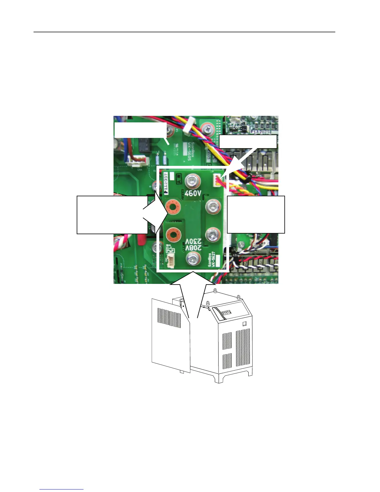
Check / Adjust Input Voltage Configuration (208/230V 460V Only)
1. The power supply includes 2 inverters each having a voltage configuration board which must be positioned to
match the primary input voltage. Failure to correctly position both boards results in a fault that blinks code 2-2
on the Status Led (front panel). Remove the power supply left side panel and locate the voltage configuration
board. The input voltage configuration is shown at the top of the board.
2. If necessary, disconnect the jumper from the top-right corner of the board, remove the board and re-install
withthe correct input voltage shown at the top of the board. Reconnect the jumper to the top-right corner of
theboard.
Art # A-04856_AB
1. Unplug connector
2. Remove bolts.
3. Invert board.
4. Re-install board.
5. Plug in connector.
208/230V / 460V
Input Voltage Board
(Shown in 460V Position)
Inverter Module