Manual 0-5057 3-7 INSTALLATION
PAK 200
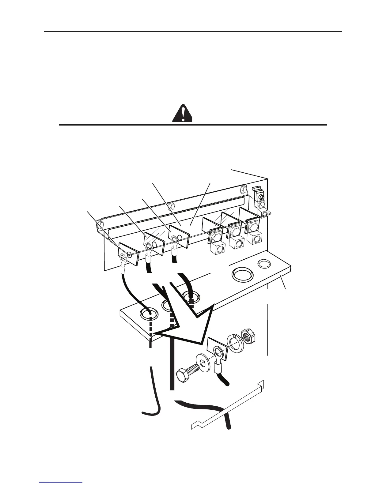
Connect Input Power and System Ground Cables
1. Carefully cut back the outer sheath on the primary input power cable to expose the individual wires. Cut back
the insulation on the individual wires. Route the cable upward through the connections cover support panel on
the rear panel of the power supply.
2. Insert the individual wires into the proper lug and tighten the nut onto the wires.
3. Pass the ground and input power cables through the leads bracket as shown. Connect the individual wires as
shown Connect the power cable ground wire to the ground terminal block.
CAUTION
The clear connections cover must remain in place.
4. If required, pass a system ground cable (F1) through the last opening in the connections cover su port panel
next to the input power cable. Connect the cable to the ground terminal block on the power supply rear panel.
Refer to the Ground Connections Section for full details and procedures on proper system grounding.
5. Re-install the connections cover on the power supply. Snug the hardware securely by hand. Do not over-
P
IL
OT
WO
R
K
TO
R
C
H
Connection Panel
AC
INPUT
L1
L2
L3
Work Lead
Torch Lead -
To Arc Starter
Work
Torch
Lead Connection Detail
Connections Cover
Support Panel
Art # A-08500
Connections Cover
Pilot
To Cutting Table
Leads Bracket
Pilot Lead -
To Arc Starter