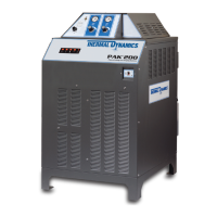
PAK 200
Manual 0-5057 4-7 OP-
Status Code Key for PAK 200
Status
Code
Message Cause/Remedy
1-1
System not Enabled or Missing AC
Input Phase
External E-Stop Activated or CCM TB1-1&2 jumper missing;
Missing AC Phase; GCM200 control cable not connected.
1-2 Pilot Ignition Failure
Pilot did not start within 15 seconds.
Plasma pressure too high; Defective Arc Starter
1-3 Lost Pilot
Pilot went out without shutoff signal; Plasma pressure too high;
cut current set too low for consumables.
1-4 Loss of Transfer
Arc transfer (>50 ms.) then arc lost with START still on. Standoff
too high; Current set too low.
1-5 Of the Plate Function not currently enabled.
1-6 Pilot Timed out w/o Transfer
Must transfer from Pilot to Cutting Arc in 85 ms. (SW8-1 OFF)
or 3 sec. (SW8-1 ON). Standoff too high or void in work under
torch; cut current too low for consumables; Plasma pressure
too low.
1-7 Not used
1-8 Tip to Electrode Voltage too low
Detected tip voltage too close to electrode voltage. Plasma flow/
pressure too low; Plasma leak; cut current too high; shorted
torch body; consumable parts worn out.
2-1 Missing Phase Blown fuse, Broken or loose connection on power cable
2-2 Wrong input voltage
Inverter(s) not configured correctly for input voltage;
Poor power quality (brownouts, dropouts);
Input power capacity / wiring too small causing voltage drop;
broken or loose power cable connections.
2-3
Inverter or Pilot Regulator Over
Temperature
Failed fan; Ambient above 40 deg C. (104 F); Blocked airflow
2-4 Power Supply not Ready Defective inverter
2-5 DC Output Low
Output less than 60 VDC; Defective inverter, shorted output;
Shorted pilot regulator (chopper); CCM voltage sense (J6) wire
open or disconnected.
2-6
Inverter primary over current or
cap voltage imbalance fault
Over current detected in inverter primary circuit, remove power
to reset; defective inverter; voltage surge;
2-7 Unexpected current
Current >20A in work or pilot leads before pilot ignition; Possible
shorted torch; Defective current sensor.
2-8
Unexpected current in pilot cir-
cuit
Current > 5A in pilot circuit; wrong or mismatched consumables;
Pilot lead shorted to negative in torch tube; Possible shorted
torch
2-9 Unexpected current in work lead
Current > 5A in work lead; Short to chassis in RAS; Negative
lead short to gnd.