Function of each device
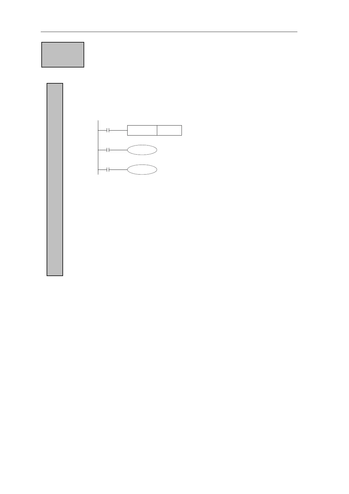
RST C0
X0
C0 K10
Y0
X1
C0
About the assignment of normally used counter and power failure retentive
counter, they could be changed in the method of changing FD parameters’
settin via the peripheral device. g
16 bits binary increment counter, its valid setting value is K1~K32,767
(Decimal constant). The set value K0 and K1 have the same meaning, i.e. act
when output contacts at the beginning of first time count.
If cut the PLC’s power, then the value
of the normally use counter will be
reset. However, counter used by power
cut retentive could save the count
value after power cut, and the counter
will go on counting from the value.
z Every time when X001 drives coil C0, the counter’s current value will
increase. When execute the coil instruction the tenth time, output contact
acts. Later, even X001 activates, counter’s current value will not change.
z If reset input X000 is ON, execute RST instruction, counter’s current
value is 0, output contacts activates.
z For the counter’s set value, it could not only set by constant K, but also be
assigned by data register’s ID. E.g. assign D10, if the content of D10 is
123, it’s the same with setting K123.
z When write the set value to the current value register via MOV instruction
etc. When input next time, output coil gets, current value register turns to
the set value.
Function
16 bits counter For normally use or power count retentive
42
 Loading...