Applied Instructions
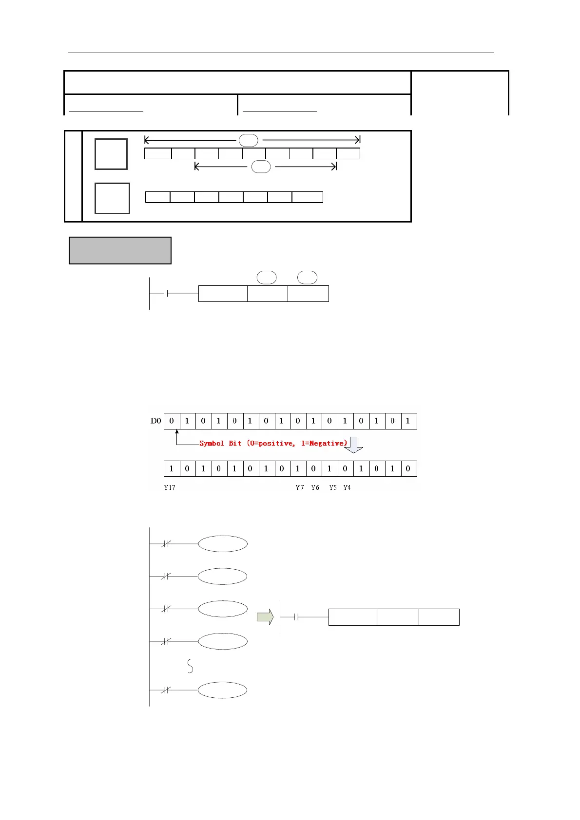
CML D0 DY0
S· D·
X0
A copy of each data bit within the source device is inverted and then moved to the designated
destination.
《Reading of inverted input》
M0
M1
M2
M3
M17
CML DX0 DM0
M8000
X0
X1
X2
X3
X17
Function & Action
The sequential control instruction i
the left could be denoted by
following CML instruction.
n
the
z Each data bit in the source device is inverted (0->1, 1->0) and sent to the destination
device. If use constant K in the source device, it can be auto convert to be binary.
z It’s available when you want to inverted output the PLC’s output
[CML]
16 bits instruction:CML 32 bits instruction:DCML
Suitable Models:
XC1、XC3、XC5
Word
Device
Bit
Device
X
Y
M
S
T
C
Dn.m
D·
S·
D
FD
DM
DX
DY
DS
TD
CD
K/H
98
 Loading...